UCAO-TECH - TRC25
Installation
Getting started with the documentation
This website centralizes the documentation for our robotics projects. You'll find detailed information on our tests in computing, mechanical, and electronic domains.
This documentation is freely accessible. It's fast, flexible, and reliable — with immediate access to information.
Main Installation
The simplest and fastest way to get started is to use our CLI tool. The CLI is also available as a standalone executable if you want to use it without installing Node.js.
                      $ npm install -g our-cli init my-project
                      $ cd my-project
                      $ our-cli start
To get started, check out the specific documentation for each domain. Each section contains installation guides, code examples, and tutorials to help you get up and running quickly.
Domain Specific Guides
For more details, refer to the dedicated pages for each section. There you'll find comprehensive information on prerequisites, configuration, and advanced use of our tools and components.
Computing
Test 1: Implementation of a Robot Management Class System
Object-oriented design and implementation of a comprehensive robot class architecture for the TEKBOT project.
1. Context
Robotics today occupies a central place in technological innovation, combining computing, electronics, and mechanics to design intelligent systems capable of interacting with their environment. This project is part of the Tekbot Robotics Challenge 2025 and constitutes the introductory test for the computing part of the competition. It involves designing and implementing an object-oriented architecture around a main Robot class, which will serve as the foundation for all future robotic developments. The approach aims to introduce students to software modeling, code structuring, and thinking about software architecture in a robotic context. The emphasis is on understanding fundamental object-oriented programming concepts and their concrete application in a technical project.
2. Objectives
The objectives are:
Design a Robot class respecting object-oriented programming principles: encapsulation, inheritance, polymorphism
Implement at least two specialized subclasses derived from the Robot class
Redefine the move() method in subclasses to illustrate polymorphism
Ensure proper encapsulation of attributes (private attributes, getters/setters)
3. Project Structure
The TEKBOT project is organized according to a modular architecture faithful to the actual folder structure:
TEKBOT Project Structure
- __init__.py
- actuator.py
- action_system.py
- robotic_arm.py
- motor.py
- __init__.py
- position.py
- robot.py
- mobile_robot.py
- __init__.py
- waste.py
- storage_manager.py
- __init__.py
- energy_manager.py
- ai.py
- intelligence_system.py
- navigation_system.py
- __init__.py
- camera.py
- sensor.py
- gyroscope.py
- perception_system.py
- temperature.py
- __init__.py
- gui.py
4. Object-Oriented Programming - Complete Implementation
The TEKBOT project illustrates the major principles of OOP through a modular and realistic architecture. Here is an educational explanation of each concept, accompanied by concrete examples from the project code.
4.0 CONSTRUCTOR – Object Initialization
Detailed definition: The constructor is a special method of a class (in Python, __init__) that is automatically called when creating a new object. It allows initializing the object's attributes with starting values, ensuring that each instance begins in a consistent state.
Example in the project:
class Robot:
                  def __init__(self, nom: str, energie: float = 100.0):
                      self._nom = nom
                      self._energie = energie
                      self._etat = "prêt"
The __init__ constructor initializes the robot's name, energy, and state upon creation.
4.1 ENCAPSULATION – Protection and Control
Detailed definition: Encapsulation is the principle of grouping data (attributes) and methods that manipulate this data within the same entity (the class). It protects the object's internal state by making certain attributes private (prefix _ or __), accessible only through public methods called accessors (getters) and mutators (setters). This allows controlling data modification and avoiding inconsistencies.
Example in the project:
class Capteur(ABC):
                  def __init__(self, id_capteur: str, type_capteur: str):
                      self._id = id_capteur.strip()      # Private attribute
                      self._type = type_capteur.strip()  # Private attribute
                      self._valeur = 0.0                 # Private attribute

                  def get_valeur(self) -> float:
                      return self._valeur

                  def set_valeur(self, v: float):
                      if v >= 0:
                          self._valeur = v
                      else:
                          raise ValueError("Invalid value")
Here, attributes are protected and access is through dedicated methods, ensuring value consistency.
4.2 INHERITANCE – Reuse and Specialization
Detailed definition: Inheritance allows creating a new class (called "child" or "derived") from an existing class (called "parent" or "base"). The child class inherits attributes and methods from the parent class, promoting code reuse and specialization. It can also redefine or extend certain behaviors.
Example in the project:
class Robot(ABC):
                  # Abstract base class

              class RobotMobile(Robot):
                  def __init__(self, nom: str, vitesse: float):
                      super().__init__(nom)  # Parent constructor call
                      self._vitesse_max = float(vitesse)
The RobotMobile class inherits from Robot and adds specific mobility-related functionalities.
4.3 POLYMORPHISM – Flexibility and Extensibility
Detailed definition: Polymorphism allows using the same interface (method or attribute) for objects of different types. Each subclass can redefine the inherited method to adapt its behavior. Thus, the same method call can produce different effects depending on the targeted object.
Example in the project:
class Capteur(ABC):
                  @abstractmethod
                  def lire_valeur(self):
                      pass

              class Camera(Capteur):
                  def lire_valeur(self):
                      # Camera specific

              class Gyroscope(Capteur):
                  def lire_valeur(self):
                      # Gyroscope specific

              # Polymorphic usage
              capteurs = [Camera(...), Gyroscope(...)]
              for capteur in capteurs:
                  capteur.lire_valeur()  # Calls method adapted to each type
The same method (lire_valeur) is called on each object, but the behavior depends on the concrete subclass.
4.4 ABSTRACTION – Simplification and Modularity
Detailed definition: Abstraction consists of defining classes or methods without concrete implementation (abstract classes or methods). It imposes a contract on subclasses, which must provide their own implementation. This helps structure code and clarify each class's responsibilities.
Example in the project:
from abc import ABC, abstractmethod

              class Robot(ABC):
                  @abstractmethod
                  def move(self):
                      pass  # Must be redefined in subclasses
The Robot class imposes the presence of the move() method in its subclasses, without providing details.
4.5 COMPOSITION & AGGREGATION – Building Complex Objects
Detailed definition: Composition and aggregation are relationships that allow building complex objects from other objects. Composition implies that the composed object owns and manages the lifecycle of its components; aggregation indicates a more flexible relationship where objects can exist independently.
Example in the project:
class ActionSystem:
                  def __init__(self):
                      self._actionneurs: Dict[str, Actionneur] = {}
                      self._moteurs: List[Moteur] = []
                      self._bras_robotiques: List[BrasRobotique] = []
The ActionSystem class is composed of Motor, RoboticArm, and Actuator objects: it orchestrates their functioning. Similarly, MobileRobot possesses subsystems like StorageManager or AI (composition/aggregation).
5. Technologies and Tools Used
5.1 Development Languages and Tools
- Python 3.11+ — Main language for object-oriented architecture and business logic
- Pygame 2.6+ — Interactive graphical simulation and robotic visualization
- VS Code — Modern and modular development environment
- Git — Version management and collaboration
5.2 Architecture, Modeling and Organization
- PlantUML — UML diagram generation (classes, sequence, activities, use cases)
- Design Patterns — Singleton, Observer, Strategy, State for software robustness
- Modular architecture — Clear separation of responsibilities in Python packages
6. Complete Collection of UML Diagrams
The UML modeling of the TEKBOT project relies on several types of diagrams, each with a specific objective in understanding and documenting the system. Here is the definition of each type of diagram used, followed by its illustration and key points.
6.1 Main Class Diagram (with packages)
Definition: The UML class diagram represents the static structure of the system: it shows classes, their attributes, methods, as well as relationships (inheritance, composition, aggregation, associations) between them. It allows visualizing the object-oriented architecture and distribution of responsibilities.
Objective: Provide an overview of the software architecture, facilitate understanding of interactions between modules, and guide code implementation.

Key points illustrated:
- Inheritance: Robot → RobotMobile, BrasRobotique
- Composition: Robot contains PerceptionSystem, ActionSystem
- Aggregation: Robot uses Navigation, StorageManager
- Polymorphism: Redefined virtual methods
- Encapsulation: Private attributes + public methods
6.2 Class Diagram (without packages)
Definition: This simplified class diagram presents only the main classes and their relationships, without the package structure, for more direct reading of OOP links.
Objective: Allow quick understanding of inheritance, composition and aggregation relationships between major project classes.

6.3 Sequence Diagram - Dynamic Interaction
Definition: The UML sequence diagram describes the temporal sequence of messages exchanged between objects during a specific scenario. It highlights the order of interactions, method calls and synchronization between components.
Objective: Illustrate the dynamic unfolding of a use case, clarify execution logic and detect potential synchronization or design problems.

Illustrated sequence:
- 1⃣ Initialization of robot and systems
- 2⃣ Perception of environment via sensors
- 3⃣ AI analysis and decision making
- 4⃣ Navigation to detected waste
- 5⃣ Collection via robotic arm
- 6⃣ Storage and automatic sorting
6.4 Activity Diagram - Processing Flow
Definition: The UML activity diagram models the control and data flows of a business process or algorithm. It highlights steps, decisions, loops and conditions that structure the unfolding of a mission or functionality.
Objective: Understand and optimize processes, identify decision points and alternatives, and document complex scenarios.

Key Takeaways
Tip: Click on the diagram to enlarge it.
Comment on the activity diagram: This activity diagram illustrates the complete unfolding of a TEKBOT robot mission, from initialization to collection and intelligent waste management. It highlights the different key steps: startup, exploration, energy management, prioritized collection and stop conditions.
6.5 Use Case Diagram - User Interactions
Definition: The UML use case diagram presents the different actors (users or external systems) and the main functionalities they have access to. It highlights possible interactions and system usage scenarios.
Objective: Identify functional needs, clarify system scope and facilitate communication between stakeholders (developers, users, clients).

Actors and use cases:
- Operator: Launch mission, monitor status, stop robot
- Technician: Configure parameters, maintenance, diagnostics
- Supervisor: Analyze performance, generate reports
- Robot (System actor): Autonomous task execution
7. Detailed Justification and Strategic Role of the 19 Project Classes
The design of the TEKBOT project is based on a rigorous object-oriented architecture, where each class plays a precise and indispensable role in the robustness, modularity and intelligence of the system. The relevance of each class is explained by its direct contribution to the separation of responsibilities, code reusability and the robot's evolution capacity. This thoughtful choice ensures a clear, evolutive architecture adapted to the challenges of modern robotics.
Robot (Abstract)
Serves as foundation for entire architecture: defines essential attributes and methods (identity, energy, state, movement interface) and imposes common contract for all robot variants.
RobotMobile
Specializes Robot class for mobility: manages autonomous navigation, path planning, orientation and dynamic speed management.
RoboticArm
Represents manipulation subsystem: encapsulates grasping, collection and object sorting logic.
Actuator
Abstraction of any device performing physical action (motor, gripper, arm, etc.). Promotes reuse and maintenance.
Motor
Specializes actuator for propulsion: manages speed, rotation direction and power.
ActionSystem
Centralizes and orchestrates all actuators: applies facade pattern to simplify control interface.
PerceptionSystem
Central sensor management system: performs data fusion, event detection and environment analysis.
Camera
Specialized sensor for vision: manages image capture, object detection and visual analysis.
Gyroscope
Orientation sensor: measures rotations, stabilizes navigation and adapts to direction changes.
Temperature
Thermal sensor: monitors environment or internal components temperature for safety.
Sensor (Abstract)
Abstract class for all sensors: imposes common interface and ensures reading consistency.
IntelligenceSystem
Robot's decision-making brain: analyzes data, plans missions, applies AI strategies.
AI
Artificial intelligence module: allows experimenting with different approaches and advanced behaviors.
NavigationSystem
Dedicated to path planning, obstacle avoidance and complex movement management.
EnergyManager
Supervises consumption, recharging and energy autonomy optimization.
Waste
Models each detected waste: stores properties (type, position, state) for intelligent management.
StorageManager
Manages storage, sorting and capacity of collected waste: optimizes onboard logistics.
GUI
Graphical User Interface: enables user interaction, real-time visualization and robot control.
Position
Represents spatial position: used for navigation, detection, movement management and graphical simulation.
Architecture Summary
This comprehensive 19-class architecture demonstrates a sophisticated object-oriented design where each component has a clear responsibility. The modular structure allows for easy maintenance, testing, and future extensions while maintaining the core principles of encapsulation, inheritance, and polymorphism throughout the system.
8. Interactive Code Extracts of Main Classes
Robot Class (core/robot.py)
class Robot(ABC):
                  """
                  Abstract Robot Class - Parent class for all robot types.

                  Integrated enumeration RobotState according to UML diagram.
                  Uses abstraction and composition principles.
                  """
                  class RobotState(Enum):
                      """
                      Enumeration of possible robot states integrated in Robot class.
                      """
                      STOPPED = auto()
                      ACTIVE = auto()
                      COLLECTING = auto()
                      SORTING = auto()
                      DELIVERING = auto()
                      MAINTENANCE = auto()
                      ENERGY_SAVING = auto()

                      def __str__(self) -> str:
                          return self.name

                      def is_operational(self) -> bool:
                          return self in [Robot.RobotState.ACTIVE, Robot.RobotState.COLLECTING,
                                        Robot.RobotState.SORTING, Robot.RobotState.DELIVERING]

                  def __init__(self, name: str):
                      if not name or not isinstance(name, str):
                          raise ValueError("Robot name must be a non-empty string")
                      self._name = name.strip()
                      self._state = Robot.RobotState.STOPPED
                      self._energy = 100.0
                      self._manual_mode = False
                      self._perception_system = None
                      self._action_system = None
                      self._navigation_system = None
                      self._energy_manager = None
                      self._gui = None
                      from .position import Position
                      self._position = Position(0.0, 0.0, 0.0)

                  # === GETTERS AND SETTERS (Encapsulation) ===
                  def get_name(self) -> str:
                      return self._name

                  def set_name(self, name: str) -> None:
                      if not name or not isinstance(name, str):
                          raise ValueError("Name must be a non-empty string")
                      self._name = name.strip()

                  def get_state(self) -> 'Robot.RobotState':
                      return self._state

                  def set_state(self, state: 'Robot.RobotState') -> None:
                      if not isinstance(state, Robot.RobotState):
                          raise ValueError("State must be of type Robot.RobotState")
                      self._state = state

                  # === METHODS ACCORDING TO UML DIAGRAM ===
                  def start(self) -> None:
                      if self._state == Robot.RobotState.STOPPED:
                          self._state = Robot.RobotState.ACTIVE
                          if self._perception_system:
                              self._perception_system.activate_perception()
                          if self._gui:
                              self._gui.log_event(f"Robot {self._name} started")
                      else:
                          raise RuntimeError(f"Cannot start robot - current state: {self._state}")

                  def stop(self) -> None:
                      self._state = Robot.RobotState.STOPPED
                      if self._perception_system:
                          self._perception_system.deactivate_perception()
                      if self._action_system:
                          self._action_system.emergency_stop()
                      if self._gui:
                          self._gui.log_event(f"Robot {self._name} stopped")

                  @abstractmethod
                  def move(self) -> None:
                      pass
Note: Complete code of this class and other project classes is available in the tekbot_classes/core/ folder of the repository.
9. Visual Simulation and Hands-on Experience
Educational Objective
The TEKBOT simulation allows experimenting and visualizing robot behavior in an interactive virtual environment. It promotes concrete understanding of navigation, collection and energy management algorithms.
How to Launch and Use the Simulation?
- Ensure you have Python 3.11+ and Pygame installed (see section 5)
- Open a terminal in the project folder
- Launch simulation with:
python tekbot_simple.py
or
python main_tekbot_simulation.py - Interact with simulation:
- Arrow keys: move robot (manual mode)
- Space: pause/resume
- R: reset simulation
- D: enable/disable debug mode
- Observe mission evolution, waste collection and real-time energy management
Simulation Videos
Main video - Nominal robot behavior
Encountered difficulties - Robot doesn't avoid all obstacles
10. References and Resources
Technical Documentation
- Python 3 Documentation - Official language reference
- Pygame Documentation - Graphics library used
- PlantUML Guide - UML diagram generation tool
Educational Resources
- OOP with Python - OpenClassrooms
- UML Diagrams Reference - Complete UML guide
- Real Python - OOP Guide
TEKBOT Robotics Challenge 2025
UCAO-TECH Team - Demonstration of Excellence in Object-Oriented Programming
"Tomorrow's robotics is built with today's fundamentals"
Computing
Test 2: Introduction to ROS2 - Sensor Data Evaluation
Implementation of ROS2 nodes for sensor data publishing, subscription, and real-time monitoring with web dashboard.
1. Introduction and Objectives
Introduction:
This project is part of an initiation test to ROS2, a modern and powerful framework for robotics and distributed systems. The goal is to discover, through concrete practice, the fundamental mechanisms of ROS2: publishing, subscribing, and inter-node communication via topics.
Educational and technical objectives:
- Understand the structure of a ROS2 package and code organization best practices
- Implement a publisher node that generates and publishes simulated sensor data (temperature, humidity, pressure) every 0.5 seconds on a dedicated topic
- Implement a subscriber node that receives this data, checks its validity against predefined ranges, and logs the result (valid/out of range)
- Create a launch file to facilitate simultaneous execution of nodes
- Gain practical experience with asynchronous communication and message management in ROS2
This test constitutes an essential foundation for any future ROS2 robotics development and allows acquiring the indispensable reflexes for designing robust, scalable, and interoperable systems.
Note: Advanced features (history, statistics, web dashboard, etc.) are personal additions to enrich the experience but are not required in the basic test.
2. ROS2 Humble Installation on Ubuntu 22.04 (Essential Step)
Before any code implementation, it is imperative to correctly install ROS2 Humble on Ubuntu 22.04.
ROS2 is a complex framework that heavily depends on the operating system version and installed distribution. ROS2 Humble is officially supported and tested on Ubuntu 22.04. Any attempt to install on another Ubuntu version or different OS may lead to incompatibilities, compilation errors, or malfunctions of ROS2 nodes and tools.
⚠️ Without a clean installation of ROS2 Humble on Ubuntu 22.04, it's impossible to guarantee the proper functioning of
ros2 commands, package compilation, or node communication.This step conditions the success of the entire project:
- Publisher and subscriber nodes cannot be launched if ROS2 is not installed or misconfigured
- The launch file will not work without the ROS2 environment initialized
- Build tools (
colcon,ament) and Python/C++ dependencies are managed by ROS2 - Documentation, tutorials, and community are centered on this version
ros2 --version command works, and properly source the environment before writing or executing any code.
- Update your system:
sudo apt update && sudo apt upgrade -y - Configure locale:
sudo apt install locales sudo locale-gen en_US en_US.UTF-8 sudo update-locale LC_ALL=en_US.UTF-8 LANG=en_US.UTF-8 export LANG=en_US.UTF-8 - Add ROS2 sources:
sudo apt install software-properties-common sudo add-apt-repository universe sudo apt update && sudo apt install curl -y sudo curl -sSL https://raw.githubusercontent.com/ros/rosdistro/master/ros.key -o /usr/share/keyrings/ros-archive-keyring.gpg echo "deb [arch=$(dpkg --print-architecture) signed-by=/usr/share/keyrings/ros-archive-keyring.gpg] http://packages.ros.org/ros2/ubuntu $(lsb_release -cs) main" | sudo tee /etc/apt/sources.list.d/ros2.list > /dev/null - Install ROS2 Humble:
sudo apt update sudo apt install ros-humble-desktop python3-argcomplete -y - Initialize environment:
echo "source /opt/ros/humble/setup.bash" >> ~/.bashrc source ~/.bashrc - Verify installation:
ros2 --version
In case of problems: Consult ROS Answers forums, Ubuntu documentation, or ask the community for help before going further in development.
3. sensor_data_evaluation Folder Structure (Real Project Example)
Here is the actual structure of the sensor_data_evaluation folder in this project, containing the ROS2 package and all associated files:
sensor_data_evaluation/
              ├── build/                         # Build folders generated by colcon
              ├── install/                       # Installation folders generated by colcon
              ├── log/                           # Colcon build logs
              ├── logs/                          # CSV data and statistics files
              │   ├── sensor_data_received.csv
              │   └── sensor_stats_python.csv
              ├── sensor_data_evaluation/        # Main ROS2 package
              │   ├── package.xml
              │   ├── setup.py / setup.cfg
              │   ├── TEST.md                    # Test documentation
              │   ├── web_monitor.py             # Flask backend for dashboard
              │   ├── launch/
              │   │   └── sensor_data_launch.py  # ROS2 launch file
              │   ├── resource/
              │   │   └── sensor_data_evaluation # ROS2 resource file
              │   ├── sensor_data_evaluation/
              │   │   ├── __init__.py
              │   │   ├── sensor_data_publisher.py   # Publisher node
              │   │   ├── sensor_data_subscriber.py  # Subscriber node
              │   │   └── sensor_stats_node.py       # Statistics node
              │   ├── templates/
              │   │   └── monitor.html               # Web dashboard
              └── ... (other automatically generated folders)
- logs/: contains CSV files generated by nodes (history, statistics)
- sensor_data_evaluation/: complete ROS2 package with source code, launch, resources, templates, test documentation and web backend
- build/, install/, log/: automatically generated during compilation with
colcon build
Why this structure?
This organization respects ROS2 standards: each package must contain a package.xml file, a setup.py (for Python), a resource/ folder (for package registration), and optionally launch/ for launch files. This ensures compatibility with ROS2 tools (colcon build, ros2 run, etc.), portability and project maintainability. The logs/ and templates/ folders facilitate traceability and web interface.
4. Detailed Functionalities
4.1 Publisher Node
Role: This node simulates a sensor by generating every 0.5s random values for temperature (14.8–35.2°C), humidity (29.8–70.2%), and pressure (949.5–1050.5 hPa), slightly extending beyond normal ranges to test system robustness. Values are published on the /sensor_data topic as a three-float array.
Utility: Test ROS2 pipeline without real hardware, validate anomaly detection and system responsiveness.
Key points: Regular publication, realistic generation, intentional range extension to simulate edge cases.
4.2 Subscriber Node
Role: Receives each message, checks if each value is within expected range (15–35°C, 30–70%, 950–1050 hPa), logs "Valid" or "Out of range" in console, and records each measurement in logs/sensor_data_received.csv with date and time.
Utility: Traceability, immediate anomaly detection, creation of exploitable historical data.
Key points: Automatic verification, detailed logging, CSV recording, easily modifiable ranges in code.
4.3 Statistics Node
Role: Calculates in real-time the average, min and max for each sensor with each new data received, and updates logs/sensor_stats_python.csv.
Utility: Synthetic view of system state, detection of drifts or anomalies over time.
Key points: Automatic calculations, CSV storage, separate stats per sensor, easy to extend.
4.4 Flask Web Dashboard
Role: Modern web interface displaying real-time curves, histograms, tables, statistics and alerts (out-of-range values) from generated CSV files.
Utility: Remote visualization, quick anomaly identification, professional user experience, graph export.
Key points: Automatic refresh (WebSocket), dark mode, responsive, visual alerts, PNG export, easy to customize.
5. Global Operation Schema
+-------------------+        +---------------------+
              | sensor_data_      |        | sensor_data_        |
              | publisher (Node)  |----->  | subscriber (Node)   |
              |  (random data)    |        |  (check, log, CSV)  |
              +-------------------+        +---------------------+
                      |                           |
                      |                           |
                      |                           v
                      |                 +---------------------+
                      |                 | sensor_stats_node   |
                      |                 | (stats, log, CSV)   |
                      |                 +---------------------+
                      |                           |
                      v                           v
              +-----------------------------------------------+
              |         CSV Files (logs/)                     |
              +-----------------------------------------------+
                      |
                      v
              +-------------------+
              |  Flask server     |
              |  (web_monitor.py) |
              +-------------------+
                      |
                      v
              +-------------------+
              | Web Dashboard     |
              | (monitor.html)    |
              +-------------------+
6. Overview of Main Nodes Code
Publisher Node Code (sensor_data_publisher.py)
import rclpy
              from rclpy.node import Node
              from std_msgs.msg import Float32MultiArray
              import random

              class SensorDataPublisher(Node):
                  def __init__(self):
                      super().__init__('sensor_data_publisher')
                      self.publisher_ = self.create_publisher(Float32MultiArray, '/sensor_data', 10)
                      self.timer = self.create_timer(0.5, self.publish_sensor_data)
                      self.get_logger().info('SensorDataPublisher node started.')

                  def publish_sensor_data(self):
                      temperature = round(random.uniform(14.8, 35.2), 2)
                      humidity = round(random.uniform(29.8, 70.2), 2)
                      pressure = round(random.uniform(949.5, 1050.5), 2)
                      msg = Float32MultiArray()
                      msg.data = [temperature, humidity, pressure]
                      self.publisher_.publish(msg)
                      self.get_logger().info(f'Published: Temp={temperature:.2f}°C, Hum={humidity:.2f}%, Press={pressure:.2f}hPa')

              def main(args=None):
                  rclpy.init(args=args)
                  node = SensorDataPublisher()
                  rclpy.spin(node)
                  node.destroy_node()
                  rclpy.shutdown()

              if __name__ == '__main__':
                  main()
Subscriber Node Code (sensor_data_subscriber.py)
import rclpy
              from rclpy.node import Node
              from std_msgs.msg import Float32MultiArray
              import os
              import csv
              from datetime import datetime

              class SensorDataSubscriber(Node):
                  def __init__(self):
                      super().__init__('sensor_data_subscriber')
                      self.subscription = self.create_subscription(
                          Float32MultiArray,
                          '/sensor_data',
                          self.listener_callback,
                          10)
                      self.get_logger().info('SensorDataSubscriber node started.')
                      self.csv_file = 'logs/sensor_data_received.csv'
                      os.makedirs('logs', exist_ok=True)
                      if not os.path.exists(self.csv_file):
                          with open(self.csv_file, 'w', newline='', encoding='utf-8') as f:
                              writer = csv.writer(f)
                              writer.writerow(['Date', 'Time', 'Temperature', 'Humidity', 'Pressure'])

                  def listener_callback(self, msg):
                      temperature, humidity, pressure = msg.data
                      temperature = float(f"{temperature:.2f}")
                      humidity = float(f"{humidity:.2f}")
                      pressure = float(f"{pressure:.2f}")
                      now = datetime.now()
                      date_str = now.strftime('%Y-%m-%d');
                      time_str = now.strftime('%H:%M:%S');
                      temp_ok = 15.0 <= temperature <= 35.0
                      hum_ok = 30.0 <= humidity <= 70.0
                      press_ok = 950.0 <= pressure <= 1050.0
                      if temp_ok and hum_ok and press_ok:
                          self.get_logger().info(f'Valid: Temp={temperature:.2f}°C, Hum={humidity:.2f}%, Press={pressure:.2f}hPa')
                      else:
                          self.get_logger().warn(f'Value out of range! Temp={temperature:.2f}°C, Hum={humidity:.2f}%, Press={pressure:.2f}hPa')
                      # Save to CSV
                      with open(self.csv_file, 'a', newline='', encoding='utf-8') as f:
                          writer = csv.writer(f)
                          writer.writerow([date_str, time_str, temperature, humidity, pressure])
Main Commands Summary Table
| Command | Description |
|---|---|
colcon build --packages-select sensor_data_evaluation |
Compile the ROS2 package |
source install/setup.bash |
Activate ROS2 environment |
ros2 launch sensor_data_evaluation sensor_data_launch.py |
Launch all nodes via launch file |
ros2 run sensor_data_evaluation sensor_data_publisher |
Launch publisher node alone |
ros2 run sensor_data_evaluation sensor_data_subscriber |
Launch subscriber node alone |
ros2 run sensor_data_evaluation sensor_stats_node |
Launch statistics node alone |
python3 web_monitor.py |
Launch Flask web server (dashboard) |
Computing
Test 3: Creating a Pathfinding Algorithm - Autonomous Navigation
Implementation of autonomous navigation system using ROS2, SLAM, and pathfinding algorithms for maze solving.
1. Context
Mobile robotics today occupies a central place in industry, research, and innovation. Robots capable of autonomous movement in complex environments are at the heart of many technological challenges, whether in logistics, exploration, assistance, or scientific research. Test 3 fits into this dynamic: it proposes to confront students with a concrete problem of autonomous navigation, as found in the professional world.
In this test, the TekBot robot evolves in an unknown environment, simulated under Gazebo, which reproduces the constraints of a real maze. The student must approach the question of robotic mobility as an engineer or researcher would: how to enable a machine to perceive, understand, and traverse a space without direct human intervention?
2. Objectives
The objective of Test 3 is to demonstrate the ability to design and implement autonomous navigation for a mobile robot (here the TekBot robot) in an unknown and constrained environment, such as a simulated maze.
- The TekBot robot must explore an unknown environment and generate a usable map for navigation.
- The robot must be capable of autonomous localization on this map, even after complex movements.
- The student must enable the robot to reach a defined target position on the map, avoiding all present obstacles.
- The solution must function without direct human intervention during the autonomous navigation phase.
- The approach must be reproducible and documented, each technical choice must be justified.
3. Workspace Configuration
3.1 Prerequisites
- Operating System: Ubuntu 22.04 LTS (recommended for ROS 2 Humble compatibility)
- ROS 2 Humble installed (official guide)
- Administrator rights (sudo) for installing necessary packages
3.2 TekBot Project Installation
- Clone the project repository
git clone https://github.com/charif-tekbot/tekbot_sim.git - Navigate to the project directory
cd tekbot_sim - Run the configuration script
source configure.sh
4. Tools and Software
4.1 Gazebo Classic
Gazebo Classic is the reference 3D simulator for mobile robotics under ROS 2. It allows testing, validating, and optimizing TekBot robot behavior in realistic virtual environments without hardware risk.
# Installation
              sudo apt update && sudo apt install gazebo11 libgazebo11-dev
              sudo apt install ros-humble-gazebo-ros-pkgs ros-humble-gazebo-ros-control

              # Launch commands
              ros2 launch tekbot_description gazebo.launch.py          # Basic robot simulation
              ros2 launch maze_solving maze.launch.py                  # Maze visualization
              ros2 launch maze_solving tekbot_maze.launch.py           # Complete simulation
4.2 RViz2
RViz2 is the essential 3D visualization tool for ROS2. It displays in real-time the robot state, sensor data (LiDAR, cameras...), generated map, trajectories, coordinate frames, etc.
# Installation
              sudo apt install ros-humble-rviz2

              # Launch
              rviz2
5. SLAM (Mapping)
SLAM (Simultaneous Localization And Mapping) is an essential component of mobile robotics. It allows a robot like TekBot to build a map of its environment while localizing itself on it, without GPS or external landmarks.
SLAM Toolbox
We chose SLAM Toolbox for this project due to its excellent balance between precision, speed, and configuration ease for 2D mapping.
# Installation
              sudo apt install ros-humble-slam-toolbox

              # Launch
              ros2 launch slam_toolbox online_async_launch.py
Practical Steps
- Launch TekBot simulation
- Start SLAM Toolbox in another terminal
- Visualize map and robot position in RViz2
- Save map after exploration completion
6. Navigation with Nav2
Nav2 (Navigation2) is the official autonomous navigation software suite for ROS2. It provides the TekBot robot with all necessary components for intelligent and safe movement in a known environment.
# Launch Nav2 with saved map
              ros2 launch nav2_bringup navigation_launch.py map:=/path/to/your/map.yaml
Key Features
- Path planning and trajectory tracking
- Dynamic obstacle avoidance
- Emergency stop management
- Real-time adaptation to unexpected events
- Modular architecture for easy sensor integration
7. A* Pathfinding Algorithm
The A* algorithm is an optimal pathfinding method widely used in mobile robotics and ROS2, particularly for autonomous navigation of robots like TekBot.
Algorithm Principle
A* combines the advantages of Dijkstra (real cost exploration) and heuristic search (remaining cost anticipation). At each step, it chooses the node with the lowest estimated total cost:
f(n) = g(n) + h(n)
              Where:
              - g(n) = actual cost from start to n
              - h(n) = estimated remaining cost (heuristic, e.g., Euclidean distance)
Step-by-Step Operation
- Initialize open list with starting point
- Repeat until target reached or exhaustion
- Select node with smallest f(n)
- If it's the target, reconstruct path
- Otherwise, move to closed list and process neighbors
In ROS2 Context
In ROS2, A* is used by Nav2's global planner to generate safe and efficient trajectories, considering the occupancy map generated by SLAM or provided by the user.
8. Results and Demonstration
Achieved Results
- Successful autonomous exploration of unknown environments
- Accurate map generation using SLAM Toolbox
- Reliable robot localization with AMCL
- Efficient path planning with A* algorithm
- Complete maze navigation and escape capability
Key Features Demonstrated
- Real-time obstacle detection and avoidance
- Dynamic path replanning
- Multi-sensor data fusion
- Robust navigation in complex environments
- Professional-grade documentation and reproducibility
9. Technologies and Tools Used
Core Technologies
- ROS2 Humble — Robot Operating System 2 framework
- Gazebo Classic — 3D simulation environment
- SLAM Toolbox — Simultaneous localization and mapping
- Nav2 — Autonomous navigation suite
Development Tools
- Ubuntu 22.04 — Operating system
- RViz2 — 3D visualization tool
- RQt — GUI tools for ROS2
- Git — Version control system
Mechanical
Test 1: CAD SolidWorks - Beginner Level
Fundamental CAD skills assessment through 3D part modeling and mechanical assembly in SolidWorks.
Objective
This test evaluates our fundamental Computer-Aided Design (CAD) skills using SolidWorks. The goal is to create, from dimensioned sketches, a set of functional 3D parts respecting material, mass, and geometric constraints, then to perform a functional mechanical assembly with center of gravity calculation.
Modeled Parts
We designed four individual parts from 2D sketches, using the software's basic tools.
Methodology Used
- 2D Sketches: Rectangles, circles, polygons, construction lines
- 3D Features:
- Extrude boss/base
- Cut extrude
- Fillets (radii)
- Mirror
- Sketch Constraints: Horizontal, vertical, tangent, coincident, symmetric
- Unit System: MMGS (mm, gram, second)
- Decimals: 2 digits after decimal point
- Holes: All through holes unless specified otherwise
Part Details
| Part | Material | Density (g/mm³) | Obtained Mass |
|---|---|---|---|
| Part 1 | Steel AISI 1020 | 0.0079 | 2850.16 g |
| Part 2 | Aluminum 1060 | 0.0027 | 279.77 g |
| Part 3 | Steel AISI 1020 | 0.0079 | 1633.25 g |
| Part 4 | Aluminum 1060 | 0.0027 | 297.29 g |
Mechanical Gripper Assembly
The mechanical gripper assembly was created in SolidWorks from components provided in the .zip file. The objective was to correctly assemble all parts while respecting the degrees of freedom necessary for the gripper's operation, particularly its opening and closing via cylinder action.
Parts Used
- Cylinder body
- Cylinder rod
- Cylinder end
- Connecting rods (left and right)
- Connecting rod pins
- Jaw holders (left and right)
- Jaws (left and right)
- Circlips (locking elements)
- M5x25 Socket Head Cap Screws
- Jaw holder pin
Main Assembly Steps
- Base Fixation
The sub-assembly containing the cylinder (body + rod + end) was inserted and fixed as a reference (immobile component). - Connecting Rods Assembly
Both connecting rods were inserted and constrained with:- Concentric: to align rotation axes with cylinder holes
- Symmetry: to ensure identical and opposite movement on both sides via the top plane
- Adding Jaw Holders and Jaws
Each jaw holder was assembled with its corresponding connecting rod:- Concentric: between jaw holder hole and connecting rod
- Coincident: to fix lateral position
- Inserting Connecting Rod Pins
Pins were used instead of screws, with constraints:- Concentric: for pin and traversed holes
- Coincident: between pin head and contact surface
- Placing Circlips
Circlips were inserted to mechanically lock pins (without adding unnecessary over-constraint).
Constraints Used
| Constraint Type | Usage |
|---|---|
| Concentric | Axis alignment (holes and pins) |
| Coincident | Contact of flat faces |
| Symmetry | Movement synchronization |
Center of Mass Analysis
The center of mass analysis helps better understand the gripper's balance in different operating positions. It was performed in SolidWorks after finalizing the assembly.
a) Minimum Cylinder Rod Position
In this position, the cylinder rod is fully retracted into the body, corresponding to the gripper closed state.
Center of Mass Coordinates (in mm):
X = -29.15
Y = 0.16
Z = 19.93
b) Maximum Cylinder Rod Position
The rod is completely extended, corresponding to the gripper open state.
Center of Mass Coordinates (in mm):
X = -25.78
Y = 0.06
Z = 19.93
Problems Encountered and Solutions
| Problem | Probable Cause | Solution Applied |
|---|---|---|
| Over-constraint of certain parts | Excessive or contradictory constraint application | Removal of redundant constraints and degree of freedom verification |
| Error when applying symmetry constraints | Incorrect face selection or wrong reference plane | Reapplication by correctly selecting both faces and the top plane |
| Blocked gripper movement | Too many fixed parts or locked constraints | Reapplication of essential constraints only (coincident and concentric) |
| Circlips preventing movement | Circlips applied with too many constraints | Adding only one constraint (e.g., concentric) to avoid blocking |
Graphic Resources & SolidWorks Files
Part 1


Part 2


Part 3


Part 4


Final Assembly

SolidWorks 2025 Source Files
These visual elements facilitate technical reading of the project and serve as modeling proof within the TRC2K25 framework.
Conclusion
This test validated our ability to:
- Model precise mechanical parts
- Apply functional materials and constraints
- Perform realistic assembly under constraints
- Evaluate properties like mass and center of gravity
This project provides a solid foundation for more complex mechanical designs within the TRC2K25 framework.
Mechanical
Test 2: CAD SolidWorks - Intermediate Level
Advanced mechanical design and parametric modeling in SolidWorks for the Tekbot Robotics Challenge 2025.
🔹 Introduction
This intermediate-level CAD test using SOLIDWORKS, conducted as part of the Tekbot Robotics Challenge 2025, allows us to practice several key skills:
- Create parametric and adaptable parts
- Modify existing geometries using advanced techniques
- Add 3D features like pockets
- Perform complete assembly while controlling mass and center of gravity
The test is divided into four phases: three part modeling stages, followed by a final assembly exercise.
All modeling is done in the MMGS environment (millimeter, gram, second) with precision to two decimal places. The material used is AISI 1020 steel, with a density of 0.0079 g/mm³.
🔧 Part I – Parametric Part Design
- a) Parameters: A = 81.00; B = 57.00; C = 43.00
File: Part1(a).SLDPRT
Mass obtained: 977.95 g
🖼️ Part Visualization
.png)
- b) Parameters: A = 84.00; B = 59.00; C = 45.00
File: Part1(b).SLDPRT
Mass obtained: 1068.75 g
🖼️ Part Visualization
.png)
Functions Used
- 2D (Sketch): Line, arc, circle, smart dimensioning, geometric relations
- 3D (Features): Extrude boss/base, extruded cut, fillet, hole wizard from sketch
✂️ Part II – Part Modification
- Updated parameters: A = 86.00; B = 58.00; C = 44.00
- Direct dimension modification in the feature tree
- Added extruded cut to remove material
- File: Partie 2.SLDPRT
- Mass obtained: 628.18 g

🧩 Part III – Pocket Addition
- Added lateral pocket to make the part asymmetric
- Created rectangular sketch on lateral face, then applied extruded cut
- File: Partie 3.SLDPRT
- Mass obtained: 432.58 g

🛠️ Assembly – Chain Links
- Download and extract the ZIP file containing the parts
- Import parts into SOLIDWORKS
- Apply necessary constraints: concentricity, coincidence, and origin alignment
Case a)
- Parameters: A = 25°; B = 125°; C = 130°
- File: Assem3.SLDASM question (a).SLDASM
- Center of gravity (mm): X = 348.66; Y = -88.48; Z = -91.40
Case b)
- Parameters: A = 30°; B = 115°; C = 135°
- File: Assem3.SLDASM question (b).SLDASM
- Center of gravity (mm): X = 327.67; Y = -98.39; Z = -102.91
📥 Download Source Files
All SOLIDWORKS files for this project are grouped in a ready-to-download ZIP archive:
📁 Archive Content
- • Part1(a).SLDPRT
- • Part1(b).SLDPRT
- • Partie2.SLDPRT
- • Partie3.SLDPRT
- • Assem3(a).SLDASM
- • Assem3(b).SLDASM
🏆 Optional Challenge
We present here the complete modeling of the optional challenge.
For this challenge, we modeled the part using basic functions as well as advanced SolidWorks features like boss, rib, extruded cut, etc., while respecting the MMGS system and the specified material (AISI 1020 steel).
3D Part View

✅ Conclusion
- Mastery of parametric modeling
- Ability to modify and enhance 3D features
- Precise management of assembly relations
- Rigorous control of mass and center of gravity
All steps have been carefully documented and saved in separate files (.SLDPRT and .SLDASM).
Mechanical
Test 3: CAD SolidWorks - Advanced Level
Expert-level parametric modeling and complex mechanical design in SolidWorks for the Tekbot Robotics Challenge 2025.
🔹 Introduction
This test aims to evaluate our ability to design a complex mechanical part in 3D using SolidWorks. It focuses on modeling, constraint and dimension management, as well as obtaining a mechanically and functionally coherent part.
The objective is to model a part from variable dimensions, ensuring that the final mass is accurate thanks to the material density. The results should reflect a deep understanding of modeling tools and good analytical skills.
📏 Modeling Parameters
- Unit system: MMGS (millimeter, gram, second)
- Material: Aluminum 1060 Alloy
- Density: 2700 kg/m³
- Holes: All through holes unless specified otherwise
- Decimals: 2
- Fillet radius: 10 mm (unless specified otherwise)
🛠️ SolidWorks Functions Used
- 2D Sketch
- Extrude Boss/Base
- Extruded Cut
- Mirror
- Linear Pattern
- Cut feature
- Mass measurement (Evaluate > Mass Properties)
- Material definition (Apply Material)
📐 Question A
- A = 193 mm; B = 88 mm
- W = 44 mm; X = 48.25 mm; Y = 93.5 mm; Z = 103 mm
- Mass obtained: 1400.64 g

📐 Question B
- A = 205 mm; B = 100 mm
- W = 50 mm; X = 51.25 mm; Y = 105.5 mm; Z = 115 mm
- Mass obtained: 1651.39 g

📐 Question C
- A = 210 mm; B = 105 mm
- W = 52.5 mm; X = 52.5 mm; Y = 110.5 mm; Z = 120 mm
- Mass obtained: 1765.22 g

📥 SolidWorks 2025 Source Files
Complete Test 3 Archive
Contains all SOLIDWORKS files for the advanced test
download Download SOLIDWORKS Files✅ Conclusion
This advanced test allowed us to consolidate our skills in parametric design, complex 3D problem solving, and precise management of physical properties. Each parameter variation highlighted the importance of rigorous modeling and clear organization in the feature tree.
Electronic
Test 1: Input Test: Gyroscope and Accelerometer
Orientation detection with MPU6050 accelerometer and gyroscope - Converting physical quantities into usable electrical signals.
Table of Contents
Test 1 (Input): Orientation Detection with Accelerometer & Gyroscope
Presentation
A sensor is an electronic device designed to convert physical or environmental quantities (motion, temperature, pressure, etc.) into usable electrical signals. Among the diversity of available sensors, this test focuses on the accelerometer and gyroscope, key components in robotics and autonomous navigation.
Key Features
- Real-time orientation detection
- I2C communication protocol
- LCD display integration
- Portable and autonomous system
Objective
This test aims to measure, interpret and display in real time the orientation and acceleration of a hand using an inertial sensor connected to a microcontroller. The data is visualized on an LCD screen via I2C communication.
Sensor Presentation
Accelerometer (MPU6050)
Measures linear acceleration on three axes (X, Y, Z), detecting speed and position variations.
- Movement detection (forward, backward, tilt)
- Trajectory correction
- Fall and impact detection
Gyroscope (MPU6050)
Measures angular velocity on three axes, determining rotation speed and direction.
- Object orientation tracking
- Movement stabilization
- Navigation precision improvement
Sensor Identification

We selected the GY-521 module, based on the MPU6050 sensor, which integrates an accelerometer and gyroscope in a single component.
Sensor Operation:
- Accelerometer: Measures acceleration in m/s² or g
- Gyroscope: Measures angular velocity in °/s
- I2C Communication: Default address 0x68
Materials Used
| Component | Reference | Quantity | Purpose |
|---|---|---|---|
| Microcontroller | Arduino UNO (ATmega328P) | 1 | System core and processing |
| Sensor | GY-521 (MPU6050) | 1 | Motion and orientation detection |
| Display | LCD 16x2 + I2C module | 1 | Real-time data visualization |
| Power Supply | 9V Battery | 1 | Portable power source |
| Wiring | Breadboard, jumpers | - | Circuit connections |
| Passive Components | 10 kΩ Resistors | 2 | I2C pull-up resistors |
Component Presentation

Arduino UNO
ATmega328P microcontroller - System brain for data processing and control.

LCD 16x2 + I2C
Real-time display of orientation and acceleration data.

Breadboard
Prototyping platform for easy circuit assembly and testing.

Jumpers
Flexible wiring for rapid prototyping and connections.

10 kΩ Resistors
I2C bus stabilization and communication reliability.

9V Battery
Portable power source with internal voltage regulation.
Electronic Schematic

Complete electronic schematic of the MPU6050 sensor system with Arduino UNO and LCD display
Overall System Operation
- Component Initialization
LCD and MPU6050 sensor setup and calibration
- Automatic Calibration
Sensor calibration at system startup
- Raw Data Reading
Continuous acceleration and orientation data acquisition
- Dominant Direction Detection
Algorithm processing for movement direction
- Direction and Intensity Display
Real-time LCD output of processed data
Technical Specifications
- Sampling Rate: 3.3 Hz (300ms delay)
- Communication: I2C at 400kHz
- Accuracy: ±2% for acceleration
- Power Consumption: ~50mA
- Operating Voltage: 5V DC
Arduino Code
Libraries Used
- Wire.h – I2C Communication
- Adafruit_MPU6050.h – Sensor Control
- Adafruit_Sensor.h – Structures and Abstractions
- LiquidCrystal_I2C.h – LCD Screen Management
Code Features
- Real-time data processing
- Automatic error handling
- Direction detection algorithm
- LCD display management
- Sensor calibration
// Test 1 - GY-521 (MPU6050) with LCD and Arduino UNO
// UCAO-TECH TRC 2025

#include <Wire.h>
#include <Adafruit_MPU6050.h>
#include <Adafruit_Sensor.h>
#include <LiquidCrystal_I2C.h>

Adafruit_MPU6050 mpu;
LiquidCrystal_I2C lcd(0x27, 16, 2);

void setup() {
  Serial.begin(115200);
  Wire.begin();
  lcd.begin();
  lcd.backlight();
  lcd.print("Sensor init...");

  if (!mpu.begin()) {
    lcd.clear();
    lcd.print("MPU6050 Error");
    while (1);
  }
  lcd.clear();
  lcd.print("MPU ready.");
  delay(1000);
}

void loop() {
  sensors_event_t a, g, temp;
  mpu.getEvent(&a, &g, &temp);

  float ax = a.acceleration.x;
  float ay = a.acceleration.y;
  float az = a.acceleration.z;

  lcd.clear();
  if (abs(ax) > abs(ay) && abs(ax) > abs(az)) {
    lcd.print(ax > 0 ? "Right" : "Left");
  } else if (abs(ay) > abs(az)) {
    lcd.print(ay > 0 ? "Forward" : "Backward");
  } else {
    lcd.print(az > 0 ? "Up" : "Down");
  }
  lcd.setCursor(0, 1);
  lcd.print("Acc: ");
  lcd.print(max(max(abs(ax), abs(ay)), abs(az)), 2);
  lcd.print(" g");
  delay(300);
}
Demonstration Videos
Main Demonstration
Axis Testing
Real-time Operation
Problems Encountered
| Problem | Root Cause | Solution Applied |
|---|---|---|
| Inconsistent display | Incorrect threshold values | Threshold adjustment and calibration |
| Incorrect orientation | Z-axis calibration error | Proper Z-axis calibration |
| Unstable LCD | Power supply fluctuations | Power supply verification and stabilization |
Conclusion
Achievements
- Applied electronics and programming skills
- Used combined accelerometer-gyroscope sensor
- Designed functional circuit with LCD interface
- Implemented real-time data processing
Downloads
UCAO-TECH TRC 2025 | Electronic Test 1 - Accelerometer & Gyroscope
Electronic
Test 2: Communication Test: The Black Box
Real-time motion data recording and transmission system using MPU6050 sensor in a cubic enclosure.
Test 2: Black Box - Communication and Control
Duration: 1 week
1. Introduction
In aerospace, automotive, and railway sectors, black boxes are essential for recording operational data. Inspired by these systems, we designed a device capable of recording and transmitting in real-time the motion data of a robot using an MPU6050 sensor (accelerometer + gyroscope) integrated into a cubic box.
2. Test Objectives
- Implement an inertial data acquisition system (MPU6050)
- Transmit data via I2C bus to a control station
- Display real-time data on an LCD screen
- Use ATmega328P microcontrollers without Arduino boards
- Document PCB design and ensure professional presentation
3. Components Used

2 × ATmega328P
System core, these 8-bit microcontrollers handle:
- I2C communication between modules
- Sensor data processing
- LCD display control
Specs: 32KB Flash, 2KB SRAM, 16MHz

1 × MPU6050 Module
6-axis sensor (gyroscope + accelerometer) used for:
- Spatial orientation detection
- Sudden movement measurement
- Earth gravity reference
I2C communication (address 0x68)

1 × 16x2 LCD Screen
Data visualization interface:
- Displays real-time data
- Controlled via I2C interface
- Typical address: 0x27 or 0x3F
Consumption: ~1mA

1 × 5V Voltage Regulator
Stabilizes power supply:
- Protects sensitive components
- Type: LM7805
Max current: 1A (with heatsink)
4. System Architecture
The system is distributed in two modules:
- Sensor module (black box): contains the I2C master ATmega328P and MPU6050
- Control station: contains the I2C slave ATmega328P and LCD screen
5. Electronic Schematics (made with KiCad)
Circuits were designed with KiCad for each subsystem of the project.
Power Supply Schematic

Black Box Schematic

Control Station Schematic

6. Printed Circuit Board
Physical circuit support: custom PCB for each module: power supply, black box, and control station.
Power Supply Board


Black Box Board


Control Station Board


KiCad Files Download
Download all KiCad source files including schematics and PCBs for the project:
download Download complete KiCad folder (RAR)7. Proteus Simulation
The MPU6050 module not being available in the official Proteus library, we simulated its behavior by directly injecting constant data into the master microcontroller (ATmega328P). This allows verification of I2C bus operation, data transmission, and LCD display.
Simulation Folder Structure
📁 Simulation_Proteus_Black_Box
              ├── 📁 master
              │   ├── master.ino
              └── 📁 slave
                  └── slave.ino
Complete Folder Download
download Download simulation project (.zip)Simulation Demonstration Video
8. Code
Black Box Side (I2C Master with MPU6050)
#define F_CPU 16000000UL
              #include <avr/io.h>
              #include <util/delay.h>
              #include <avr/interrupt.h>

              #define MPU6050_ADDR 0x68
              #define SLAVE_ADDR 0x20

              // === I2C Master ===
              void I2C_Init() {
                  TWSR = 0x00;
                  TWBR = 72; // 100kHz at 16MHz
              }

              void I2C_Start() {
                  TWCR = (1 << TWINT) | (1 << TWSTA) | (1 << TWEN);
                  while (!(TWCR & (1 << TWINT)));
              }

              void I2C_Stop() {
                  TWCR = (1 << TWINT) | (1 << TWSTO) | (1 << TWEN);
                  _delay_us(10);
              }

              void I2C_Write(uint8_t data) {
                  TWDR = data;
                  TWCR = (1 << TWINT) | (1 << TWEN);
                  while (!(TWCR & (1 << TWINT)));
              }

              uint8_t I2C_Read_ACK() {
                  TWCR = (1 << TWINT) | (1 << TWEN) | (1 << TWEA);
                  while (!(TWCR & (1 << TWINT)));
                  return TWDR;
              }

              uint8_t I2C_Read_NACK() {
                  TWCR = (1 << TWINT) | (1 << TWEN);
                  while (!(TWCR & (1 << TWINT)));
                  return TWDR;
              }

              // === MPU6050 ===
              void MPU6050_Init() {
                  I2C_Start();
                  I2C_Write(MPU6050_ADDR << 1);  // Write mode
                  I2C_Write(0x6B); // PWR_MGMT_1
                  I2C_Write(0);    // Wake up
                  I2C_Stop();
              }

              int16_t MPU6050_ReadAxis(uint8_t regH) {
                  I2C_Start();
                  I2C_Write(MPU6050_ADDR << 1);  // Write
                  I2C_Write(regH);               // Register to read
                  I2C_Start();
                  I2C_Write((MPU6050_ADDR << 1) | 1); // Read
                  uint8_t high = I2C_Read_ACK();
                  uint8_t low = I2C_Read_NACK();
                  I2C_Stop();
                  return (int16_t)(high << 8 | low);
              }

              int main() {
                  DDRB |= (1 << PB5); // Debug LED
                  I2C_Init();
                  MPU6050_Init();

                  while (1) {
                      int16_t accX = MPU6050_ReadAxis(0x3B);
                      int16_t accY = MPU6050_ReadAxis(0x3D);
                      int16_t accZ = MPU6050_ReadAxis(0x3F);

                      // Send data to slave
                      I2C_Start();
                      I2C_Write(SLAVE_ADDR << 1); // Slave
                      I2C_Write(accX >> 8); I2C_Write(accX & 0xFF);
                      I2C_Write(accY >> 8); I2C_Write(accY & 0xFF);
                      I2C_Write(accZ >> 8); I2C_Write(accZ & 0xFF);
                      I2C_Stop();

                      PORTB ^= (1 << PB5);
                      _delay_ms(300);
                  }
              }
Control Station Side (I2C Slave + 4-bit LCD)
#define F_CPU 16000000UL
              #include <avr/io.h>
              #include <avr/interrupt.h>
              #include <util/delay.h>
              #include <stdio.h>

              #define LCD_PORT PORTD
              #define LCD_DDR DDRD
              #define RS PD0
              #define EN PD1

              volatile int16_t accX, accY, accZ;
              volatile uint8_t data_received = 0;

              // === 4-bit LCD Functions ===
              void LCD_Command(uint8_t cmd) {
                  LCD_PORT = (LCD_PORT & 0x0F) | (cmd & 0xF0);
                  LCD_PORT &= ~(1 << RS);
                  LCD_PORT |= (1 << EN);
                  _delay_us(1);
                  LCD_PORT &= ~(1 << EN);
                  _delay_us(200);

                  LCD_PORT = (LCD_PORT & 0x0F) | (cmd << 4);
                  LCD_PORT |= (1 << EN);
                  _delay_us(1);
                  LCD_PORT &= ~(1 << EN);
                  _delay_ms(2);
              }

              void LCD_Char(char data) {
                  LCD_PORT = (LCD_PORT & 0x0F) | (data & 0xF0);
                  LCD_PORT |= (1 << RS);
                  LCD_PORT |= (1 << EN);
                  _delay_us(1);
                  LCD_PORT &= ~(1 << EN);
                  _delay_us(200);

                  LCD_PORT = (LCD_PORT & 0x0F) | (data << 4);
                  LCD_PORT |= (1 << RS);
                  LCD_PORT |= (1 << EN);
                  _delay_us(1);
                  LCD_PORT &= ~(1 << EN);
                  _delay_ms(2);
              }

              void LCD_Init() {
                  LCD_DDR = 0xFF;
                  _delay_ms(50);
                  LCD_Command(0x02);
                  LCD_Command(0x28);
                  LCD_Command(0x0C);
                  LCD_Command(0x06);
                  LCD_Command(0x01);
              }

              void LCD_Print(char *str) {
                  while (*str) {
                      LCD_Char(*str++);
                  }
              }

              // === ISR for I2C reception ===
              ISR(TWI_vect) {
                  static uint8_t buffer[6];
                  static uint8_t index = 0;

                  switch (TWSR & 0xF8) {
                      case 0x60: // Slave address received (Write)
                          index = 0;
                          TWCR |= (1 << TWEA) | (1 << TWINT);
                          break;
                      case 0x80: // Data received
                          buffer[index++] = TWDR;
                          if (index >= 6) {
                              accX = (buffer[0] << 8) | buffer[1];
                              accY = (buffer[2] << 8) | buffer[2];
                              accZ = (buffer[4] << 8) | buffer[5];
                              data_received = 1;
                              index = 0; // Reset index after reception
                          }
                          TWCR |= (1 << TWEA) | (1 << TWINT);
                          break;
                      default:
                          TWCR |= (1 << TWEA) | (1 << TWINT);
                          break;
                  }
              }

              int main() {
                  DDRB |= (1 << PB1); // LED debug for reception signal
                  LCD_Init();

                  // I2C as slave
                  TWAR = (0x20 << 1);  // Slave address 0x20
                  TWCR = (1 << TWEA) | (1 << TWEN) | (1 << TWIE);
                  sei(); // Global interrupts

                  char text[16];

                  while (1) {
                      if (data_received) {
                          LCD_Command(0x80); // Line 1
                          sprintf(text, "X:%4d Y:%4d", accX, accY);
                          LCD_Print(text);

                          LCD_Command(0xC0); // Line 2
                          sprintf(text, "Z:%4d", accZ);
                          LCD_Print(text);

                          PORTB ^= (1 << PB1);  // Blink LED for debug
                          data_received = 0;
                      }
                  }
              }
9. Explanation: Simulation vs Reality
This section aims to establish a clear correspondence between what was simulated in Proteus and what happens in the real implementation of the project.
a. Proteus Simulation
- In the simulation environment, two ATmega328P microcontrollers communicate via I2C bus:
- The master microcontroller generates random data simulating accelerometer values (accX, accY, accZ).
- This data is transmitted via I2C to a slave microcontroller, which displays it on a 16x2 LCD.
- LEDs allow visualization of system activity:
- The master LED lights up after each transmission.
- The slave LED blinks with each complete data reception.
- The simulation thus validates the communication protocol logic (I2C), reception, and data display, without needing real hardware.
b. Real Implementation with MPU6050
- In the physical version:
- The master no longer uses random data, but retrieves real acceleration values from the MPU6050 sensor, connected via I2C.
- The data read from the MPU6050 is then sent in exactly the same way to the slave via I2C.
- The slave remains unchanged: it receives 6 bytes (2 per axis) and displays them on the same LCD.
10. Demonstration Video
11. Constraints and Recommendations
- Do not use Arduino boards or breadboards in the final version
- 7 cm cubic box with top opening if opaque
- Clean wiring and securely fixed components
- Separate control station with clearly visible screen
12. Evaluation Criteria
| Criterion | Details | Points |
|---|---|---|
| Circuitry | Schema quality, soldering, power supply, circuit presentation | 25 |
| Code | Readability, comments, code logic | 25 |
| Physical realization | Aesthetics of the box and control station | 10 |
| Operation | Quality of system demonstration | 25 |
| Documentation | Structure, clarity, technical rigor | 10 |
| Oral presentation | Slides, oral expression, question response | 5 |
13. Technical References
Links to technical documents (datasheets) used in this project:
- ATmega328P – Datasheet (Microchip)
- MPU6050 – Datasheet (TDK InvenSense)
- HD44780 LCD Screen – Datasheet
- LM7805 – Datasheet (STMicroelectronics)
14. Conclusion
This test allowed the implementation of an embedded system capable of measuring and transmitting inertial data in real time. It fits into a logic of reliability, technical rigor, and integration into an autonomous robotic solution.
Electronic
Test 3: Output Test: Creating a 7-Segment Display with Servomotors
Mechanical 7-segment display reinvented using servomotors - A fusion of digital logic and mechanical motion.
7-Segment Servo Display Documentation
1. Project Context
In a world dominated by digital screens and LEDs, Tekbot Robotic Challenge 2025 launches a bold challenge: reinvent the 7-segment display by giving it a mechanical soul.

Project Origin:
TEKBOT ROBOTIC CHALLENGE 2025
2. Project Objectives
Main Objectives
- Design a fully mechanical 7-segment display
- Precisely control 7 servomotors with a microcontroller
- Implement cyclic counting 0→9→0
Secondary Objectives
- Reduce pin count using integrated circuits
- Document the development process
- Validate the solution through simulation
3. Part 1: Physical Implementation
3.1 Components Used
| Component | Reference | Quantity | Role |
|---|---|---|---|
| Microcontroller | ATmega328P | 1 | System brain |
| Servomotors | SG90 | 7 | Segment control |
| Regulator | LM7805 | 1 | 5V regulation |
| Battery | Li-ion 7.4V | 1 | Power supply |
| Capacitors | 100nF, 1000μF, 10µF | 4 | Filtering |
| Crystal | 16MHz | 1 | Clock |
3.2 Electronic Schematic

Description:
- Overvoltage protection
- Direct servo connection to PWM pins
- Reset circuit with push button


Power Supply
The power supply system includes:
- Li-ion 7.4V 2S Battery: Main power source
- LM7805 Regulator: Stabilization to 5V for components
- Filtering capacitors: 100nF and 10μF to smooth power supply
3.3 PCB Realization


Characteristics:
- Designed with KiCad
- Double-sided
- 0.6 mm tracks
- Optimized spacing for connectors
3.4 Arduino Code
Extract of main code using millis() for non-blocking timing:
// Progressive servo initialization
              if (!initTerminee) {
                if (millis() - debutInit >= 100) { // Delay between servos
                  debutInit = millis();
                  servoEnCours++;

                  if (servoEnCours < 7) {
                    segments[servoEnCours].attach(brochesServos[servoEnCours]);
                    segments[servoEnCours].write(90);
                  } else {
                    initTerminee = true;
                    afficher(chiffreActuel); // Display initial 0
                  }
                }
}3.5 Demonstration Video
4. Part 2: Theoretical Innovation
4.1 Planned Architecture

Key Components:
- 74HC138: 3→8 line decoder
- 74HC574: Latch register
- NPN Transistors (e.g., 2N2222)
- Base resistors (10kΩ)
System Operation
This system implements a mechanical 7-segment display based on servomotors, controlled with a minimum of microcontroller pins thanks to the combined use of two integrated circuits: the 74HC138 decoder and the 74HC574 latch register.
The ATmega328P uses a single PWM output (pin D6) to generate control pulses for the servos. Each segment of the display is associated with a servomotor, totaling 7 servos for the 7 segments (A to G).
The 74HC138 is a 3-to-8 decoder: from 3 address lines (A0, A1, A2), it activates a single output among Y0 to Y7. In this project, only outputs Y0 to Y6 are used, each corresponding to a segment (thus a servo). These 74HC138 outputs cannot directly switch the PWM signal, so they are connected to NPN transistors via base resistors.
void selectionnerServoInverse(uint8_t index) {
                uint8_t inverse = 7 - index; // Bit inversion
                digitalWrite(SELECTION_A, inverse & 0x01);
                digitalWrite(SELECTION_B, (inverse >> 1) & 0x01);
                digitalWrite(SELECTION_C, (inverse >> 2) & 0x01);
              }
The 74HC574 is a latch register that captures the state of inputs D0 to D6 when a pulse is applied to its clock pin (latch). When a segment is selected by the 138, the microcontroller sends a PWM pulse. This pulse is transferred via the transistor to input Dx of the 74HC574, and a clock pulse allows locking this value to output Qx of the register, which is connected to the corresponding servomotor.
// Generate PWM pulse and lock
              void envoyerImpulsionEtVerrouiller(uint16_t dureeImpulsion) {
                digitalWrite(PWM_SORTIE, HIGH);
                delayMicroseconds(dureeImpulsion);
                verrouiller(); // Capture during HIGH state
                digitalWrite(PWM_SORTIE, LOW);
              }

              // Register locking
              void verrouiller() {
                digitalWrite(HORLOGE_VERROU, LOW);
                delayMicroseconds(5);
                digitalWrite(HORLOGE_VERROU, HIGH);
                delayMicroseconds(5);
                digitalWrite(HORLOGE_VERROU, LOW);
              }
The ATmega328P repeats this sequence for each segment:
- Selection with the 138
- PWM sending
- Locking via the 574
The servos being refreshed periodically (every 20 ms), the display remains stable. This setup allows controlling 7 servos with a single PWM pin, while minimizing ATmega328P resource usage.
4.2 Proteus Simulation
The simulation validates:
- Segment selection logic
- PWM signal timing
- Microcontroller interface
Download the folder containing Arduino code and Proteus schematic file:
download Download Complete Document5. Comparison and Advantages
| Aspect | Physical Version | Optimized Version |
|---|---|---|
| Pins used | 7 PWM pins | 3 pins + 1 PWM |
| Consumption | 800mA | ~700mA (estimated) |
| Complexity | Low | Moderate |
Advantages of the Optimized Solution
- Economy of precious pins on the microcontroller
- Scalable architecture for multiple displays
- Better isolation of control signals
- Possibility of temporal multiplexing
6. Problems Encountered
- Servomotor synchronization: Variable delays in servo response requiring recalibration
- Unstable power supply: Voltage drops during simultaneous movement of multiple servos
7. Technical References
Datasheets
Software Tools
8. Conclusion
This project demonstrated the feasibility of a mechanical digital display controlled by servomotors. The main lessons are:
- The direct physical solution offers simple implementation but limits scalability
- The approach with integrated circuits allows significant resource optimization
- Energy consumption remains the main challenge for embedded applications
Gallery
Our Work Gallery
A collection of images and videos showcasing our robotics projects and team activities.
Project Showcase
Explore our journey through various robotics challenges and see the innovative solutions we've developed.
Project Photos Coming Soon
Video Demonstrations Coming Soon
Final Test
Final Test: Intelligent Automatic Sorting Conveyor System
Innovative solution for industrial waste sorting using advanced detection and automation technologies.
Project Context
The TRC 2025 (Tekbot Robotics Challenge) is an international competition that challenges student teams to develop innovative robotic solutions.
Project Details
- Duration: 1 month
- Evaluation criteria: Innovation, Functionality
- Teamwork: 10 multidisciplinary members
Project Objectives
Design an intelligent conveyor capable of automatically detecting and sorting four types of waste.
Color Detection
Using an advanced color sensor to identify different types of waste based on their dominant hue.
Servo Sorting
Automated sorting system using servomotors to precisely direct detected objects to the appropriate collection area.
Web Interface
Complete dashboard for real-time operation monitoring, sorting statistics, and remote system control.
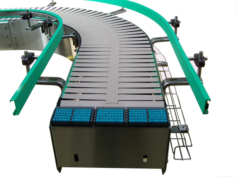
What is a Conveyor?
A conveyor is a mechanical device that automatically transports objects or materials from one point to another, used in many fields to facilitate movement and handling.
These mechanized systems form the backbone of modern handling in various sectors: food processing, logistics, automotive, and recycling. Their adoption allows radical optimization of production flows.
Productivity
Up to 300% increase in throughput compared to manual handling
Profitability
Typical ROI in 12-18 months through labor savings
Safety
80% reduction in handling-related accidents
Sustainability
Energy optimization with variable speed motors
Conveyor History
The evolution of material transport systems through the ages
Manual Conveyors
Before 1800 - Material transport by human or animal force, using baskets, wheelbarrows, and carts.
Chain Conveyors
From 1800 - First mechanized systems using chains to move materials in mines and factories.
Belt Conveyors
Early 1900s - Introduction of rubber conveyor belts, revolutionizing mass production.
Modern Automation
Early 2000s - Integration of sensors, AI, and computerized control systems for intelligent and autonomous conveyors.
Conveyor Types
Varied solutions adapted to each specific need

Belt Conveyor
Continuous system using an endless belt to transport materials.

Roller Conveyor
Series of parallel rollers for palletized or containerized loads.
Chain Conveyor
Uses chains to pull pallets or carts.

Screw Conveyor
Rotating helix to move granular or powdery materials.
Our Strategic Choice for TRC 2025
Faced with the challenge requirements, our selection focused on a modular belt conveyor, offering the best compromise between performance, precision, and adaptability to competition constraints.
TRC Criteria
Optimal response to sorting, speed, and reliability requirements
Modularity
Adaptable to 4 waste categories with quick reconfiguration
Performance
Throughput compliant with expectations with safety margin
Integration
Solution compatible with all required subsystems

Why a Belt Conveyor for Our Project?
After thorough analysis of different options, the motorized belt conveyor emerged as the optimal solution for our waste sorting system.
- Ease of design and manufacturing for our team
- Perfect compatibility with Arduino components for control
- Movement precision necessary for waste positioning
- Flat surface ideal for color sensor detection
- Possibility to easily integrate lateral sorting mechanisms

The 3 Key Project Domains
A multidisciplinary approach for a complete solution
Electronics
- Use ATmega328P or Arduino Nano as microcontroller
- Integrate color sensor for waste identification (4 colors)
- Implement detection system (laser KY-008 or photoresistor)
- Design optimized PCB with KICAD (no breadboard)
- Lithium battery power supply
Computing
- Develop waste sorting algorithm by color
- Create real-time web interface with sorted waste quantities
- Integrate TEKBOT and TRC 2025 logos in interface
- Ensure microcontroller ↔ web interface communication
- Optimize code (avoid blocking functions)
Mechanical
- Model conveyor in SolidWorks (650mm long, 100mm high)
- Provide guidance system for cube sorting (30mm)
- Validate feasibility for 3D printing/assembly
- Perform mechanical simulation (bonus)
- Document technical choices and constraints
Control Interface
Discover Our Control Interface
The computing team developed an advanced web interface for real-time conveyor monitoring and control.
Access DashboardOther Tests & Documented Projects
In addition to the conveyor presented here, our team regularly carries out other tests and prototypes, all carefully documented and made available on our GitHub space.
You can find our project history, technical files, source codes, and experience feedback.

Final Test - Computing
IT Documentation - Intelligent Conveyor System
Advanced software architecture and real-time control system for automated waste sorting.
Introduction
Context
In a world where sustainable waste management is becoming a major challenge for industrial cities, TEKBOT CITY aims to implement an innovative system to optimize waste sorting and recovery. Automated sorting, flow traceability, and digital tool integration are now essential to meet environmental, economic, and regulatory requirements.
Vision and Perspectives
The ambition of this project is to demonstrate how technological innovation can transform industrial waste management. In the short term, the goal is to implement a reliable, automated, and connected system capable of sorting different types of waste in real-time.
Documentation Approach
This documentation was designed to ensure transparency, reproducibility, and continuous improvement of the project. It details each stage of the design, from technical choices to development methods.
System Description
General Presentation
The intelligent conveyor system presented here is an innovative automated waste sorting solution, designed to meet the challenges of Industry 4.0 and sustainable development.
sequenceDiagram
                participant Operator as Operator
                participant Object as Waste (colored cube)
                participant PresenceSensor as Presence Sensor
                participant Conveyor as Conveyor
                participant ColorSensor as Color Sensor
                participant Microcontroller as Microcontroller
                participant WebInterface as Web Interface
                participant Collector as Collector

                Operator->>Object: Places waste on conveyor
                Object->>PresenceSensor: Passage detected
                PresenceSensor-->>Microcontroller: Presence signal
                Microcontroller->>Conveyor: Belt startup
                Conveyor->>Object: Transport to analysis zone
                Object->>ColorSensor: Arrival under sensor
                ColorSensor-->>Microcontroller: Color measurement
                Microcontroller->>WebInterface: Counter update
                Conveyor->>Object: Stop at end of path
                Collector->>Object: Collects waste
System Objectives
- Automatically detect object presence and color
- Autonomously classify and sort waste
- Ensure complete operation traceability
- Provide web supervision interface
System Advantages
- Automated, fast, and reliable sorting
- Adaptability to different waste types
- Reduction of manual interventions
- Data collection and analysis
Intelligent Detection
Color Detection with TCS34725
The TCS34725 sensor is an electronic component capable of identifying an object's color by analyzing the light it reflects. By decomposing this light into its components (red, green, blue), the sensor determines the dominant hue.
#include <Wire.h>
            #include <Adafruit_TCS34725.h>

            Adafruit_TCS34725 tcs = Adafruit_TCS34725();

            String detectColorTCS34725() {
                uint16_t r, g, b, c;
                uint8_t r_norm, g_norm, b_norm;
                const float gamma = 2.5;

                tcs.getRawData(&r, &g, &b, &c);

                // Normalization
                if (c > 0) {
                    r_norm = (uint32_t)r * 255 / c;
                    g_norm = (uint32_t)g * 255 / c;
                    b_norm = (uint32_t)b * 255 / c;
                } else {
                    r_norm = g_norm = b_norm = 0;
                }

                // Gamma correction
                uint8_t r_gamma = pow(r_norm / 255.0, 1.0 / gamma) * 255.0;
                uint8_t g_gamma = pow(g_norm / 255.0, 1.0 / gamma) * 255.0;
                uint8_t b_gamma = pow(b_norm / 255.0, 1.0 / gamma) * 255.0;

                // Color identification
                if (r_gamma > 180 && g_gamma < 120 && b_gamma < 120) return "Red";
                if (g_gamma > 180 && r_gamma < 120 && b_gamma < 120) return "Green";
                if (b_gamma > 180 && r_gamma < 120 && g_gamma < 120) return "Blue";
                if (r_gamma > 180 && g_gamma > 180 && b_gamma < 120) return "Yellow";
                return "Unknown";
            }
Presence Detection with KY-008 + LDR
A presence sensor detects whether an object is in a specific area. In our conveyor, we use a KY-008 laser and photoresistor combination to instantly detect object passage.
#define LASER_PIN 8
            #define LDR_PIN A0
            #define THRESHOLD 400

            bool detectPresence(int ldrPin, int threshold, int nbValidations = 3) {
                int counter = 0;
                for (int i = 0; i < nbValidations; i++) {
                    int ldrValue = analogRead(ldrPin);
                    if (ldrValue < threshold) {
                        counter++;
                    }
                    delay(20);
                }
                return (counter == nbValidations);
            }

            void setup() {
                pinMode(LASER_PIN, OUTPUT);
                pinMode(LDR_PIN, INPUT);
                digitalWrite(LASER_PIN, HIGH);
            }

            void loop() {
                if (detectPresence(LDR_PIN, THRESHOLD)) {
                    Serial.println("Presence confirmed!");
                    // Action to perform
                }
                delay(100);
            }
Conveyor Automation
Automation Architecture
The system architecture relies on embedded intelligence that controls the entire sorting process: detection, identification, orientation, and tracking.
#include <Wire.h>
            #include <Adafruit_TCS34725.h>
            #include <Servo.h>

            // Pin definitions
            #define LASER_ENTRY_PIN 2
            #define LDR_ENTRY_PIN A0
            #define LASER_EXIT_PIN 3
            #define LDR_EXIT_PIN A1
            #define SERVO_SORT1_PIN 8
            #define SERVO_SORT2_PIN 9

            Adafruit_TCS34725 tcs = Adafruit_TCS34725();
            Servo servoSort1;
            Servo servoSort2;

            void setup() {
                // Pin initialization
                pinMode(LASER_ENTRY_PIN, INPUT);
                pinMode(LDR_ENTRY_PIN, INPUT);
                pinMode(LASER_EXIT_PIN, INPUT);
                pinMode(LDR_EXIT_PIN, INPUT);

                // Servo initialization
                servoSort1.attach(SERVO_SORT1_PIN);
                servoSort2.attach(SERVO_SORT2_PIN);

                // Color sensor initialization
                if (tcs.begin()) {
                    Serial.println("TCS34725 sensor detected!");
                }

                Serial.begin(9600);
            }

            void loop() {
                // Entry presence detection
                if (detectEntryPresence()) {
                    activateConveyor();

                    // Color detection
                    String color = detectColor();
                    sortObject(color);

                    // Data transmission
                    sendData(color, "RUNNING");
                }

                // Exit presence detection
                if (detectExitPresence()) {
                    stopConveyor();
                    sendData("NONE", "STOPPED");
                }
            }
Error Management
Error Cases
- No object detected
- Color detection error
- Atypical or non-conforming objects
- Sensor hardware failure
Solutions
- Validation over multiple measurements
- Special "error" sorting bin
- Adaptive detection thresholds
- Emergency stop and alerts
Web Interface
Dashboard Presentation
The web interface developed with HTML, CSS, JavaScript, and Bootstrap offers a modern, fluid, and responsive user experience for real-time monitoring of sorting operations.
Technologies Used
- Frontend: HTML5, CSS3, JavaScript, Bootstrap
- Backend: Firebase (Realtime Database)
- Communication: WebSocket, REST API
- Microcontroller: ESP8266 + Arduino
Main Features
- Real-time counter display
- Sorting statistics visualization
- User and access management
- Data export for analysis
Firebase Integration
Firebase provides a complete platform for real-time synchronization between the microcontroller and web interface, ensuring instant data updates.
// Firebase Configuration
            const firebaseConfig = {
                apiKey: "your-api-key",
                authDomain: "your-project.firebaseapp.com",
                databaseURL: "https://your-project.firebaseio.com",
                projectId: "your-project",
                storageBucket: "your-project.appspot.com",
                messagingSenderId: "123456789",
                appId: "your-app-id"
            };

            // Initialization
            const app = firebase.initializeApp(firebaseConfig);
            const db = firebase.database();

            // Real-time change listening
            db.ref('counters').on('value', (snapshot) => {
                const data = snapshot.val();
                updateDashboard(data);
            });

            function updateDashboard(data) {
                // Interface update
                document.getElementById('counter-red').textContent = data.red || 0;
                document.getElementById('counter-green').textContent = data.green || 0;
                document.getElementById('counter-blue').textContent = data.blue || 0;
                document.getElementById('counter-yellow').textContent = data.yellow || 0;
            }
Conclusion and Perspectives
Summary
This intelligent conveyor project has demonstrated the feasibility of automated, reliable, and connected waste sorting. The integration of modern technologies has enabled the creation of a complete solution addressing industrial and environmental challenges.
Future Evolutions
Technical Improvements
- Integration of additional sensors (weight, RFID)
- AI implementation for optimization
- Security and access management enhancement
- Large-scale deployment
Future Applications
- Extension to other sorting types
- Integration into smart urban networks
- Logistical and industrial applications
- Contribution to circular economy
Acknowledgments
We would like to thank the entire UCAO-TECH team for their commitment, creativity, and professionalism in realizing this innovative project. This collective success paves the way for future technological innovations serving sustainable development.
UCAO-TECH - TRC 2025
Last updated:
Final Test - Electronic
Electronic Control System for Intelligent Conveyor
Advanced circuit design and sensor integration for precise object detection and automated sorting.
Introduction
This document presents the electronic implementation of the intelligent conveyor system for waste sorting. The system uses a modular architecture with distinct functional blocks for power supply, detection, processing, and actuation.
Main Components
- Arduino Nano (ATmega328P) - System core
- ESP8266MOD-12 - WiFi communication
- 7805 and 7812 Regulators - Power management
- Photoresistor + KY-008 - Object detection
- 12V Stepper motor + L298N - Conveyor movement
- Servomotor - Sorting mechanism

Fig. 1 - Overall view of the electronic system
System Architecture
System Architecture

Functional Description
Power Supply
Battery voltage conversion to 12V for motors and 5V for logic circuits with precise regulation
Object Detection
KY-008 laser barrier with photoresistor for precise detection at ±1mm
Real-time Processing
Arduino Nano with optimized algorithm for latency < 5ms
Data Flow
Electronic Components
Complete Component List
| Component | Reference | Quantity | Main Function | Key Characteristics |
|---|---|---|---|---|
| Arduino Nano | ATmega328P | 1 | Main controller | 16MHz, 32KB Flash, 14 I/O, 8 analog |
| WiFi Module | ESP8266MOD-12 | 1 | Wireless communication | 802.11 b/g/n, UART, 80mA TX |
| 12V Regulator | LM7812 | 1 | Motor power supply | 1A max, TO-220, 14-35V in |
| 5V Regulator | LM7805 | 1 | Logic power supply | 1A max, TO-220, 7-25V in |
| Photoresistor | GL5528 | 1 | Light detection | 10kΩ (light), 1MΩ (dark) |
| Laser Module | KY-008 | 1 | Object detection | 650nm, 5mW, 50cm range |
| Stepper Motor | 28BYJ-48 | 1 | Conveyor movement | 12V, 2048 steps/rev, 3.5kg.cm |
| Motor Driver | L298N | 1 | Motor control | 2A/channel, 46V max, dual H-bridge |
| Servomotor | SG90 | 1 | Sorting mechanism | 180°, 4.8-6V, 0.1s/60° |
| Battery | Li-ion 4S | 1 | Mobile power supply | 14.8V, 2000mAh, 4A max |
Power Supply
Main Power Supply Circuit

Fig. 3 - Power supply circuit schematic
This circuit provides the necessary voltages for all components:
- 4S Lithium Battery 14.8V: Main power source
- 7812 Regulator: Stabilizes voltage to 12V for stepper motor and Arduino NANO via VIN pin
- 7805 Regulator: Provides 5V for sensors and servomotors
- Protections:
- Reverse polarity diode
- Stabilization capacitors (475µF + 100nF)
Input Block
Complete Functional Schematic

Fig. 4 - Complete input block architecture
Processing Block
Central Architecture

Fig. 5 - Processing block functional schematic
Output Block
Actuator Schematic

Fig. 6 - Actuation systems architecture
Complete Electronic Schematic
Main Circuit

Fig. 7 - Complete system schematic (click to enlarge)
Final PCB

Fig. 8 - PCB layout

Fig. 9 - Top layer view
Physical Prototype

Fig. 11 - Overall view of the prototype

Fig. 12 - Interconnection details
Software Implementation
Configuration, Setup and Loop
// === Pin definitions ===
#define START_PHOTO_PIN A1
#define STOP_PHOTO_PIN A2
#define BUTTON_PIN 12
#define LED_PIN 7
#define IN1 8
#define IN2 9
#define IN3 10
#define IN4 11

#include <Wire.h>
#include <Adafruit_TCS34725.h>

Adafruit_TCS34725 tcs = Adafruit_TCS34725();
const int bleu = 3;
const int rouge = 4;
const int jaune = 5;
const int vert = 6;

const int threshold = 450;
const int stepDelay = 5;
const unsigned long longPressTime = 2000;

bool systemActive = false;
unsigned long buttonPressTime = 0;

void setup() {
  pinMode(IN1, OUTPUT);
  pinMode(IN2, OUTPUT);
  pinMode(IN3, OUTPUT);
  pinMode(IN4, OUTPUT);
  pinMode(BUTTON_PIN, INPUT);
  pinMode(LED_PIN, OUTPUT);

  stopMotor();
  digitalWrite(LED_PIN, LOW);

  Serial.begin(9600);
  Serial.println("System ready. Waiting...");

  if (tcs.begin()) {
    Serial.println("TCS34725 sensor detected!");
    tcs.setInterrupt(false);
  } else {
    Serial.println("TCS34725 sensor error");
    while (1);
  }

  pinMode(bleu, OUTPUT);
  pinMode(rouge, OUTPUT);
  pinMode(jaune, OUTPUT);
  pinMode(vert, OUTPUT);

  digitalWrite(rouge, LOW);
  digitalWrite(bleu, LOW);
  digitalWrite(jaune, LOW);
  digitalWrite(vert, LOW);
}

void loop() {
  Serial.print("Start sensor: ");
  Serial.print(analogRead(START_PHOTO_PIN));
  Serial.print(" | Stop sensor: ");
  Serial.println(analogRead(STOP_PHOTO_PIN));

  handleButton();

  if (!systemActive && detectStartSensor()) {
    activateSystem("START detection → Activation");
  }

  if (systemActive && detectStopSensor()) {
    deactivateSystem("STOP detection → Stop");
  }

  if (systemActive) {
    stepMotor();
    delay(stepDelay);

    String color = detectColorTCS34725();
    Serial.print("Color detected: ");
    Serial.println(color);
  }
}
Serial Communication with ESP8266 for Web Interface
The Arduino Nano transmits sorting data to the ESP8266 NodeMCU via serial link. This data is then displayed on the web dashboard, including color counters, sorting position, and last waste processing time.
// Global counters
int compteurRouge = 0, compteurVert = 0, compteurJaune = 0, compteurBleu = 0;

void envoyerDonneesWeb(String couleur, int position) {
  if (couleur == "Rouge") compteurRouge++;
  else if (couleur == "Vert") compteurVert++;
  else if (couleur == "Jaune") compteurJaune++;
  else if (couleur == "Bleu") compteurBleu++;

  Serial.print("{\"couleur\":\"");
  Serial.print(couleur);
  Serial.print("\",\"position\":");
  Serial.print(position);
  Serial.print(",\"compteurs\":{\"Rouge\":");
  Serial.print(compteurRouge);
  Serial.print(",\"Vert\":");
  Serial.print(compteurVert);
  Serial.print(",\"Jaune\":");
  Serial.print(compteurJaune);
  Serial.print(",\"Bleu\":");
  Serial.print(compteurBleu);
  Serial.println("}}");
}Testing and Validation
Test Plan
- Power Test: Measure 12V, 5V and 3.3V voltages under load
- Detection Test: Verify object detection at different distances
- Color Test: Validate identification of 4 colors
- Motor Test: Verify precise conveyor movement
- Sorting Test: Validate sorting mechanism for each color
- WiFi Test: Verify data transmission to web interface
Demonstration
Video: Complete system operation
Downloads
Complete Files
Download all source files for modification or manufacturing:
Conclusion
Technical Summary
The electronic system meets project requirements:
- Reliable object and color detection
- Precise actuator control
- Stable communication with web interface
- Sufficient autonomy (>3 hours)
Future Perspectives
Possible Improvements
- Addition of backup battery
- Integration of additional sensors
- Power consumption optimization
- Complete wireless version
Final Test - Mechanical
Mechanical Design & Fabrication - Intelligent Conveyor System
Precision engineering and robust construction for reliable automated sorting operations.
Introduction
Project Context
This mechanical documentation covers the design and implementation of an intelligent conveyor system for automated waste sorting as part of the TEKBOT Robotics Challenge 2025.
Key Objectives
- Design a 650mm conveyor system for 30mm sorting cubes
- Implement reliable mechanical sorting mechanism
- Ensure compatibility with electronic and computing systems
- Optimize for 3D printing and rapid prototyping
Complete conveyor assembly
Material Selection Strategy
Primary Materials Used
PLA Filament
Primary structural material
100% infill for critical parts
PVC Conveyor Belt
120mm width, 2mm thickness
Optimal grip for cubes
6300-2RS Bearings
Sealed ball bearings
12mm inner diameter
Material Advantages
- Cost Reduction: 60% cheaper than metal solutions
- Production Time: 3x faster manufacturing
- Maintenance: Simplified part replacement
- Weight: Lightweight yet robust structure
Component Specifications
| Component | Material | Dimensions | Quantity | Function |
|---|---|---|---|---|
| Main Frame | PLA | 650×200×150mm | 1 | Primary structure |
| Left/Right Supports | PLA | 225×100×12mm | 6 sections | Side frame elements |
| Drive Drum | PLA | Ø60mm | 1 | Motor connection |
| Return Drum | PLA | Ø60mm | 1 | Belt guidance |
| Bearings | Steel | 12×35×11mm | 4 | Rotation support |
| Sorting Guides | PLA | Various | 6 | Object direction |
CAD Modeling & Design
SolidWorks Implementation

Complete conveyor assembly in SolidWorks
Design Features
- • Parametric design for easy modifications
- • Motion study for mechanism validation
- • Interference detection implemented
- • Mass properties analysis
Key Components
Main Frame Structure
Modular aluminum-inspired PLA design with corner reinforcement.
Sorting Mechanism
Servo-actuated gates with precise 45° angular control.
Collection System
Four separate bins with guided chutes for sorted objects.
Component Gallery

Support Section A

Drive Drum

Sorting Guide

Bearing Housing
Fabrication Process
3D Printing
All custom components are 3D printed using PLA filament with 0.2mm layer height and 20-100% infill depending on structural requirements.
Frame Assembly
Modular frame assembly using interlocking PLA components with M4 stainless steel fasteners for structural integrity.
Mechanism Integration
Servo motors mounted with custom brackets, belt system tensioning, and bearing installation for smooth operation.
Final Assembly & Testing
Complete system integration followed by rigorous testing to ensure reliable operation under various conditions.
Technical Specifications
Dimensional Specifications
Performance Metrics
Validation Results
All mechanical components meet or exceed design specifications with safety margins:
- Structural safety factor: > 2.5 on all PLA components
- Bearing life expectancy: > 10,000 hours at design load
- Belt tension maintained within ±10% of optimal range
- All moving parts operate within specified tolerances
Design Files & Documentation
SolidWorks Source Files
Complete CAD project with all parts and assemblies:
- 42 individual part files (.SLDPRT)
- Main assembly and sub-assemblies
- Technical drawings and specifications
- Motion study simulations
3D Printing Files
Ready-to-print STL files for all components:
- Optimized for FDM 3D printing
- Pre-supported where necessary
- Printing guidelines included
- Assembly instructions
Important Notes
- Software Requirements: SolidWorks 2025 or compatible viewer for source files
- Printing Recommendations: 20-40% infill for non-structural parts, 80-100% for load-bearing components
- Material: PLA recommended for all printed parts
- Tolerances: Account for 0.2mm printing tolerance in assemblies
Physical Prototype & Testing
Prototype Demonstration
Conveyor system in operation
Testing Results
Successful Tests
- Continuous 8-hour operation without failure
- Accurate sorting of 30mm cubes by color
- Stable belt tracking and tension
- Proper servo mechanism response
Areas for Improvement
- Belt slippage at higher speeds
- Noise reduction in gear mechanisms
- Enhanced vibration damping
- Optimized bearing lubrication
Prototype Gallery

Complete Assembly

Mechanical Detail

Testing Phase

Technical View
Conclusion
The mechanical design of the intelligent conveyor system successfully meets all TRC 2025 requirements, demonstrating robust construction, reliable operation, and seamless integration with electronic and computing subsystems.
Key Achievements
- Precision manufacturing using 3D printing technology
- Optimized material selection for cost and performance
- Successful integration of mechanical and electronic systems
- Comprehensive documentation and reproducibility
Future Enhancements
- Advanced vibration damping systems
- Modular design for easy scalability
- Enhanced material options for specific applications
- Integration with Industry 4.0 standards
UCAO-TECH - TRC 2025
Innovative Mechanical Solutions for Automated Sorting Systems