
Test 3
Dieser Inhalt ist noch nicht in deiner Sprache verfügbar.
3rd Test
Section titled “3rd Test”Objectives
Section titled “Objectives”Design and build an innovative 7-segment display using 7 servomotors instead of traditional LEDs. Each segment of the digit is represented by a dedicated servo. The system must display digits from 0 to 9, then from 9 back to 0, with one second per change.
Technical Objectives
Section titled “Technical Objectives”- Use 7 servomotors, one for each segment of the digit.
- Display digits from 0 to 9, then from 9 to 0 automatically.
- Respect a 1-second interval between digit changes.
- Do not use blocking functions such as
delay()in the Arduino code. - Power the circuit with lithium batteries.
- Control the servos using a standalone ATmega328P microcontroller (no Arduino boards allowed in the final design).
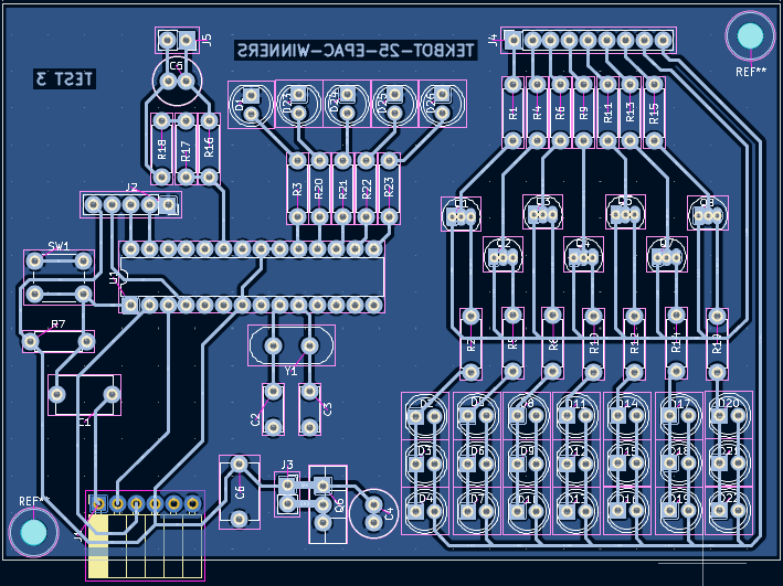
- Design the full schematic and PCB using KiCad**, including:
- Schematic diagram
- PCB layout
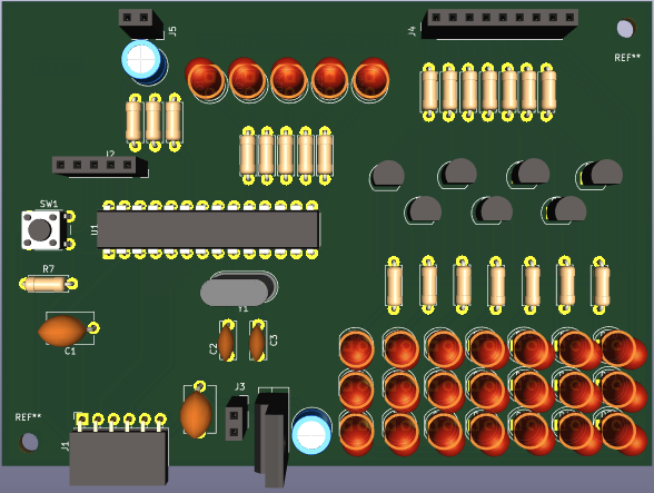
- 3D render of the board
- Design and 3D print a protective and functional casing to house the display and servos.
Additional Notes
Section titled “Additional Notes”- We may use a PCA9685 module to simplify PWM control for the servos.
- The use of Arduino boards or breadboards in the final assembly is strictly forbidden.
Summary
Section titled “Summary”Files available for download
Section titled “Files available for download”Download the KiCad and Arduino files by following these links :
KiCad
- KiCad Files : KiCad file
Arduino
- Arduino code : Arduino file
Materials
Section titled “Materials”| Category | Component | Quantity | Notes |
|---|---|---|---|
| Microcontroller | ATmega328P | 1 | Used as standalone (no Arduino board) |
| Clock | 16 MHz Crystal Oscillator | 1 | Paired with two 22 pF capacitors |
| 22 pF Capacitor | 2 | For the crystal oscillator | |
| Servomotors | SG90 Micro Servo or equivalent | 7 | One per digit segment |
| PWM Module | PCA9685 | 1 | For controlling servos and LEDs via I2C |
| LED Display | Red/Green/Blue LEDs | 7+4 | 7 for segments, 4 for battery level indicator |
| Current-limiting Resistors | Multiple | For LEDs and transistor bases | |
| Transistors | 2N2222A (or 2N2219 for simulation) | 7 | For LED brightness modulation |
| Battery Pack | 3.7 V, 3 Ah Lithium Cells | 4 | 2S2P configuration → 7.4 V, 6 Ah total |
| Battery Charging | TP4056 Charger Modules | 4 | One per lithium cell |
| Voltage Regulation | LM2596 Buck Converter | 1 | Steps down 7.4 V to 5 V |
| Voltage Divider | Resistors (custom values) | 2 | For battery voltage measurement via ADC |
| Programming Interface | 6-pin FTDI Header | 1 | To upload code to ATmega328P |
| Reset Circuit | Push Button + Pull-up Resistor | 1 | For manual microcontroller reset |
| Bootloader Indicator | LED + Resistor | 1 | Connected to Lbuilt pin to confirm bootloader presence |
| Enclosure | 3D Printed Casing | 1 | Designed in Fusion 360 |
| Connectors/Wiring | Jumper Wires, Headers, Terminals, etc. | Various | For electrical connections |
Process
Section titled “Process”Power Supply Design
Section titled “Power Supply Design”We are using a power supply system based on rechargeable lithium batteries.
To achieve this, we are using four 3.7V, 3Ah lithium cells, arranged in a 2S2P configuration:
- 2 cells in series, then duplicated in parallel.
Battery Pack Configuration
Section titled “Battery Pack Configuration”- Nominal voltage: 7.4V
- Capacity: 6Ah
- Fully charged voltage: 8.4V
Voltage Regulation
Section titled “Voltage Regulation”The battery pack powers the input of a buck converter (LM2596), which regulates the voltage down to:
- 5V output
- Max current: 3A
Battery Monitoring
Section titled “Battery Monitoring”A voltage divider is used to monitor the battery voltage.
- At 8.4V (fully charged), the measured voltage is 5V
→ This is the maximum allowed input for the ATmega328P ADC (Analog to Digital Converter).
This monitoring function allows us to:
- Estimate the battery state of charge
- Ensure safe and optimal performance of the system
Power Distribution
Section titled “Power Distribution”The regulated 5V output is then distributed across the different DC buses of the circuit.
Hardware design
Section titled “Hardware design”Circuit principal – Architecture matérielle
Section titled “Circuit principal – Architecture matérielle”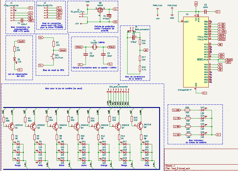
 |  |
|---|---|
 | 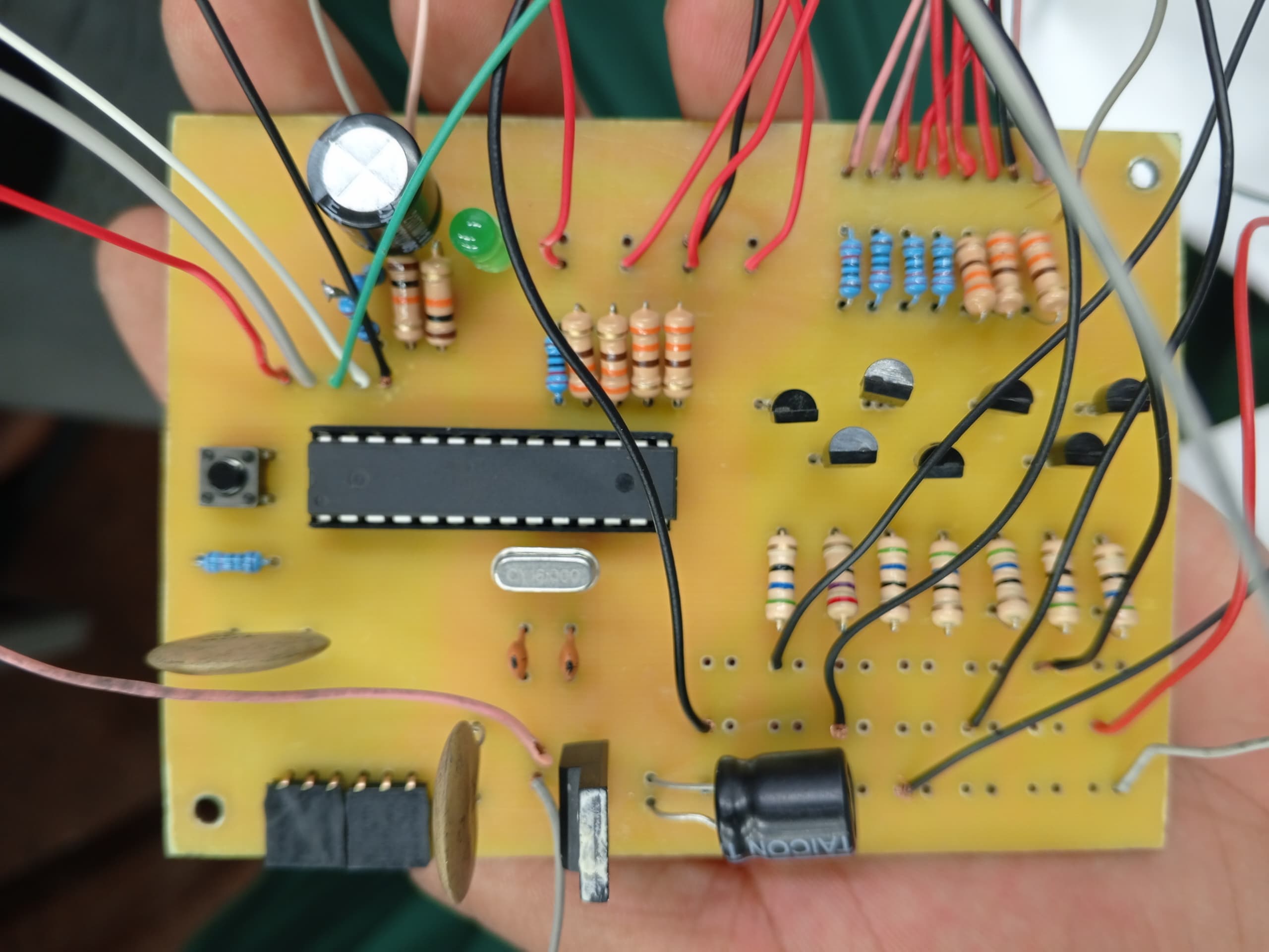 |
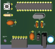
The ATMega328P microcontroller is powered by a 5V DC supply provided by a Buck converter (LM2596), represented in the schematic by the connector located near the transistor. A 16 MHz crystal oscillator, along with two 22 pF capacitors, provides the clock signal for the microcontroller.
 |  |
|---|
LED D1, connected to the Lbuilt pin, is used to verify the presence of the bootloader on the microcontroller. The push-button SW1, together with a pull-up resistor, enables manual reset of the microcontroller.
 |  |
|---|
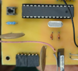
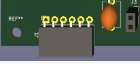
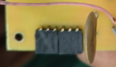
A 6-pin header allows connection to an FTDI programmer for uploading code to the microcontroller. A second 5-pin header provides I2C communication and power supply to the PCA9685 module.
 |  |
|---|
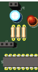
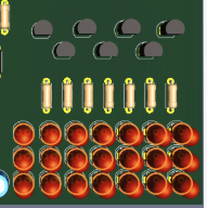
The battery monitoring circuit is based on a resistive voltage divider, which taps a fraction of the battery voltage. Using this voltage and the known divider ratio, the battery charge level can be estimated and displayed through LEDs D23 to D26.
 |  |
|---|
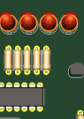
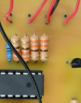
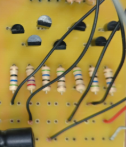
An additional network composed of transistors and LEDs has been implemented to introduce an innovative feature. The LEDs forming digit segments will vary in brightness depending on the signal applied to the bases of 2N2219 transistors (used in simulation; 2N2222A will be used in the final implementation). These transistors, controlled by the PCA9685 module, allow the brightness of the LEDs connected to their collectors to be modulated.
 |  |
|---|
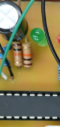
Current-limiting resistors for both the LEDs and transistor bases have been carefully calculated to ensure stable and optimal operation of the circuit.
Lithium Battery Charging System
Section titled “Lithium Battery Charging System”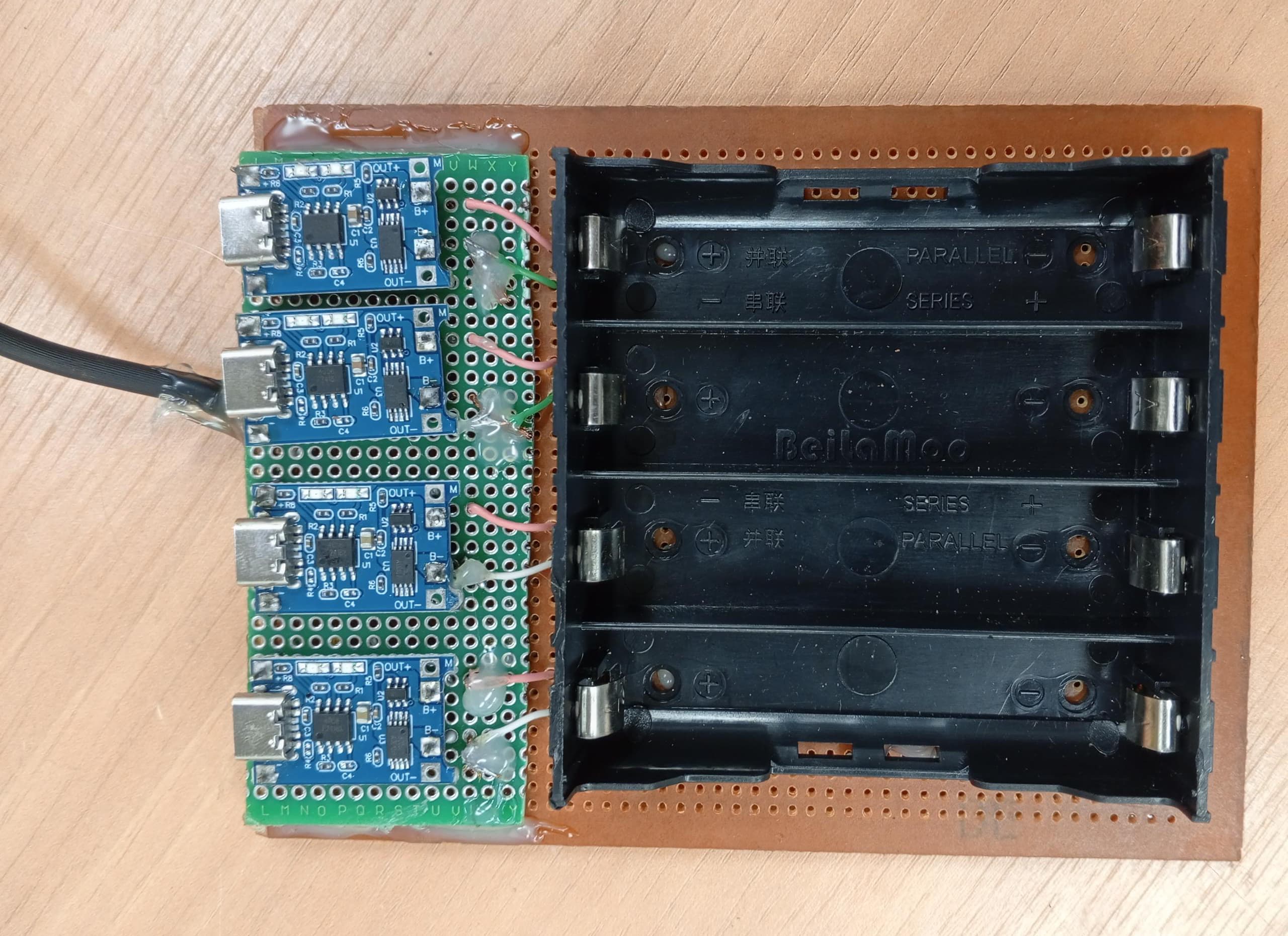
The charging system consists of four lithium battery charger modules (such as TP4056 or similar), each dedicated to an individual battery. Each module’s output is connected directly to the terminals of its respective lithium cell.
- Module Inputs: All inputs are connected in parallel to the 5 V power supply, which was also used during Test 1 and Test 2 to charge the batteries.
- Module Outputs: Each output is routed to a separate lithium battery, enabling independent and balanced charging.
This modular approach ensures:
- Simplified wiring
- Independent protection per battery
- Reduced risk of overcharging or imbalance between cells
It provides a safe, scalable, and efficient charging solution for powering the system.
Software design
Section titled “Software design”This Arduino code controls an innovative physical 7-segment display combining servomotors, LEDs with fade effects, and a battery indicator.
Code Structure
Section titled “Code Structure”Libraries and Configuration
Section titled “Libraries and Configuration”#include <Wire.h>#include <Adafruit_PWMServoDriver.h>Wire.h: I2C communication with the PCA9685Adafruit_PWMServoDriver.h: PCA9685 module control
Servo Configuration
#define SERVO_MIN 100 // 0° position#define SERVO_MAX 500 // 180° positionint angleOn = 90; // Angle for active segmentint angleOff = 0; // Angle for inactive segmentThese values define the PWM range for servomotors. Values 100-500 correspond to pulse widths for 0° and 180°.
PCA9685 Channel Mapping
Section titled “PCA9685 Channel Mapping”const int segments[7] = {0, 1, 2, 3, 4, 5, 6}; // Servo segments A-Gconst int ledChannels[7] = {8, 9, 10, 11, 12, 13, 14}; // LED segments A-Gconst int batteryLEDs[4] = {9, 10, 11, 12}; // Battery indicator LEDsImportant: Battery LEDs use the same channels as some segment LEDs (9-12).
Pattern Tables
Section titled “Pattern Tables”Servomotor Table
const bool servos[12][7] = { {1,0,0,1,0,1,1}, // Pattern 0 {0,1,1,0,1,0,1}, // Digit 0 {1,1,1,1,0,1,1}, // Digit 1 // ... etc};Each row represents a digit (0-11), each column a segment (A-G).
1= segment activated (servo at 90°)0= segment deactivated (servo at 0°)
LED Table
const bool leds[12][7] = { // Identical to servo table for now // But can be modified independently};Allows separate control of lighting and physical positioning.
Main Functions
Section titled “Main Functions”Setup - Initialization
Section titled “Setup - Initialization”void setup() { pwm.begin(); pwm.setPWMFreq(50); // 50Hz for servos
// Initialize segment states for (int i = 0; i < 7; i++) { currentSegmentState[i] = leds[currentDigit][i]; previousSegmentState[i] = currentSegmentState[i]; }
displayDigit(currentDigit); currentDigit += 1;}Main Loop - Multi-task Management
Section titled “Main Loop - Multi-task Management”Digit Change Management
if (currentMillis - previousMillis >= interval) {  // Save previous states for fade  for (int i = 0; i < 7; i++) {    previousSegmentState[i] = currentSegmentState[i];    currentSegmentState[i] = leds[currentDigit][i];  }
  displayDigit(currentDigit);  // Move servos
  fadeStartTime = currentMillis;  fadeActive = true;           // Start LED fade
// Back-and-forth logic (0→11→0) currentDigit += direction; if (currentDigit > 11) { currentDigit = 11; direction = -1; } else if (currentDigit < 0) { currentDigit = 0; direction = 1; }}Timing: Change every 1 second (interval = 1000)
LED Fade Animation
if (fadeActive) { updateLEDFade(currentMillis);}The fade runs in parallel for 1 second while servos move.
Battery Monitoring
if (currentMillis - lastBatteryCheck >= batteryCheckInterval) { lastBatteryCheck = currentMillis; updateBatteryLevel();}Timing: Check every 500ms for smooth monitoring.
Detailed Functions
Section titled “Detailed Functions”displayDigit() - Servo Control
Section titled “displayDigit() - Servo Control”void displayDigit(int number) { for (int i = 0; i < 7; i++) { if (servos[number][i]) { setServoAngle(segments[i], angleOn); // 90° } else { setServoAngle(segments[i], angleOff); // 0° } }}Instantly positions all servos according to the digit pattern.
updateLEDFade() - LED Animation
Section titled “updateLEDFade() - LED Animation”Fade Logic
void updateLEDFade(unsigned long currentMillis) {  unsigned long elapsed = currentMillis - fadeStartTime;
  if (elapsed >= fadeDuration) {    // Fade complete - final states    fadeActive = false;    for (int i = 0; i < 7; i++) {      if (currentSegmentState[i]) {        pwm.setPWM(ledChannels[i], 0, 4095); // 100%      } else {        pwm.setPWM(ledChannels[i], 0, 0);    // 0%      }    }  } else {    // Fade in progress    float progress = (float)elapsed / fadeDuration; // 0.0 → 1.0
    for (int i = 0; i < 7; i++) {      int brightness = 0;
      if (currentSegmentState[i] && !previousSegmentState[i]) {        // FADE IN: 0 → 4095        brightness = (int)(4095 * progress);      } else if (!currentSegmentState[i] && previousSegmentState[i]) {        // FADE OUT: 4095 → 0        brightness = (int)(4095 * (1.0 - progress));      } else if (currentSegmentState[i] && previousSegmentState[i]) {        // STAYS ON        brightness = 4095;      } else {        // STAYS OFF        brightness = 0;      }
      pwm.setPWM(ledChannels[i], 0, brightness);    }  }}
Fade Types:
- Fade IN: Segment turning on (0% → 100%)
- Fade OUT: Segment turning off (100% → 0%)
- Constant: Segment that doesn’t change state
updateBatteryLevel() - Battery Indicator
Section titled “updateBatteryLevel() - Battery Indicator”ADC Reading and Conversion
void updateBatteryLevel() {  int adcValue = analogRead(batteryPin);              // 0-1023  float voltage = (adcValue / 1023.0) * 5.0;         // 0-5V  float batteryPercent = (voltage / maxVoltage) * 100.0; // % based on 4.9V max
  // Constrain 0-100%  if (batteryPercent > 100.0) batteryPercent = 100.0;  if (batteryPercent < 0.0) batteryPercent = 0.0;
LED Display Logic
  // Turn off all battery LEDs  for (int i = 0; i < 4; i++) {    pwm.setPWM(batteryLEDs[i], 0, 0);  }
  // Turn on according to level  if (batteryPercent >= 75.0) {    // 4 LEDs: channels 9,10,11,12    for (int i = 0; i < 4; i++) {      pwm.setPWM(batteryLEDs[i], 0, 4095);    }  } else if (batteryPercent >= 50.0) {    // 3 LEDs: channels 10,11,12    for (int i = 1; i < 4; i++) {      pwm.setPWM(batteryLEDs[i], 0, 4095);    }  } else if (batteryPercent >= 25.0) {    // 2 LEDs: channels 11,12    for (int i = 2; i < 4; i++) {      pwm.setPWM(batteryLEDs[i], 0, 4095);    }  } else if (batteryPercent > 0.0) {    // 1 LED: channel 12    pwm.setPWM(batteryLEDs[3], 0, 4095);  }}
Display Levels:
- ≥75%: 🟢🟢🟢🟢 (4 LEDs)
- 50-74%: 🔴🟢🟢🟢 (3 LEDs)
- 25-49%: 🔴🔴🟢🟢 (2 LEDs)
- 1-24%: 🔴🔴🔴🟢 (1 LED)
- 0%: 🔴🔴🔴🔴 (0 LED)
Technical Features
Section titled “Technical Features”Timing and Performance
Section titled “Timing and Performance”- Display: Change every 2 seconds
- LED Fade: 1 second smooth transition
- Battery: Check every 500ms
- PWM: 50Hz for servos, 12-bit resolution (0-4095) for LEDs
Memory Management
Section titled “Memory Management”- Non-blocking: Uses
millis()instead ofdelay() - Multi-tasking: Simultaneously handles servos, LEDs, and battery
- Saved States: Enables intelligent fade transitions
Flexibility
Section titled “Flexibility”- Separate Tables: Independent servo/LED control
- Customizable Patterns: 12 configurable digits
- Extensible: Easy to add new effects
Practical Usage
Section titled “Practical Usage”This code creates a unique 7-segment display that combines:
- Physical movement of segments via servomotors
- Dynamic lighting with smooth fade transitions
- Real-time battery monitoring
- Continuous animation with back-and-forth effect
The result is a spectacular display where segments move mechanically while progressively lighting up!
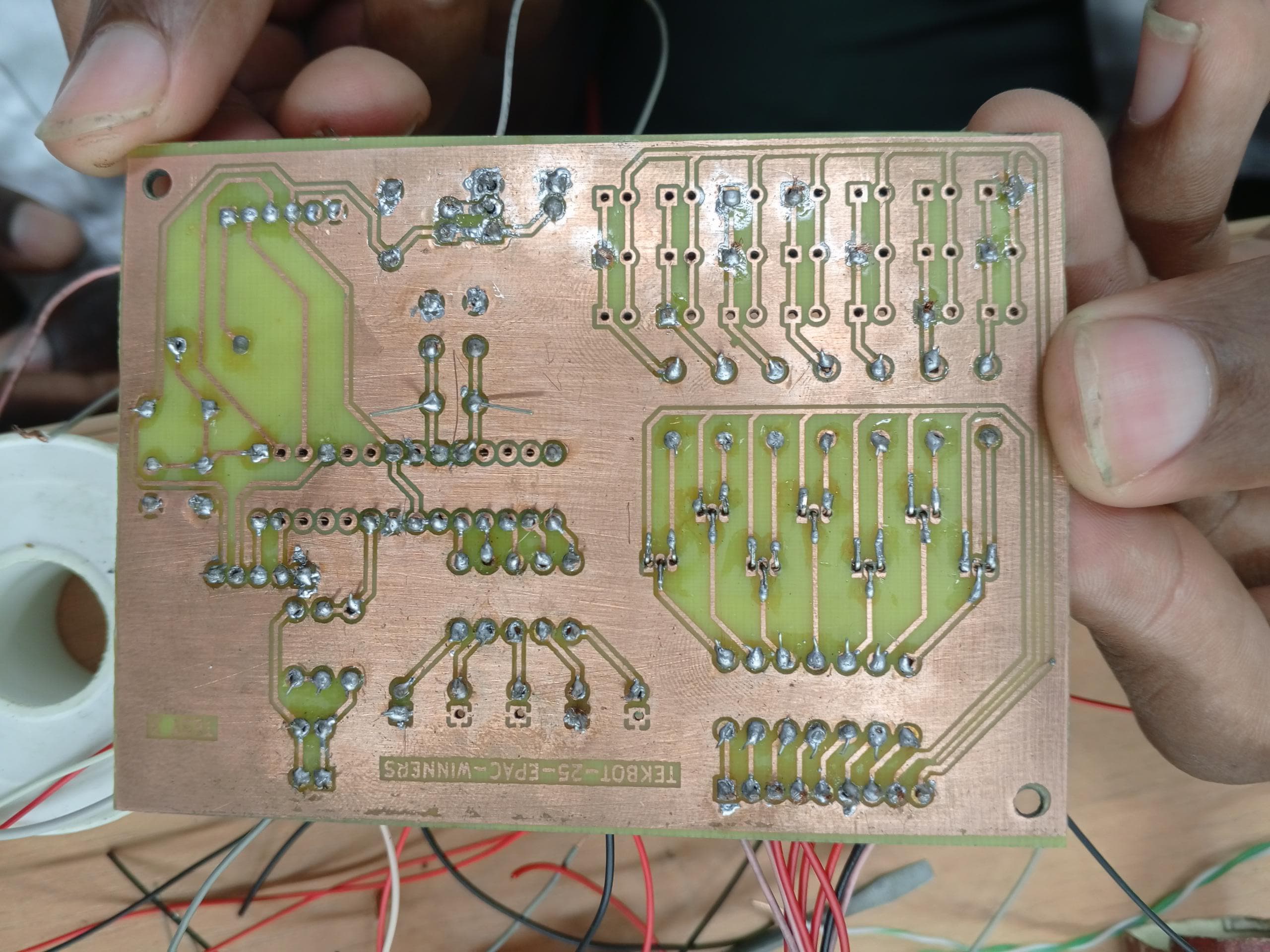
Pictures
Section titled “Pictures” | 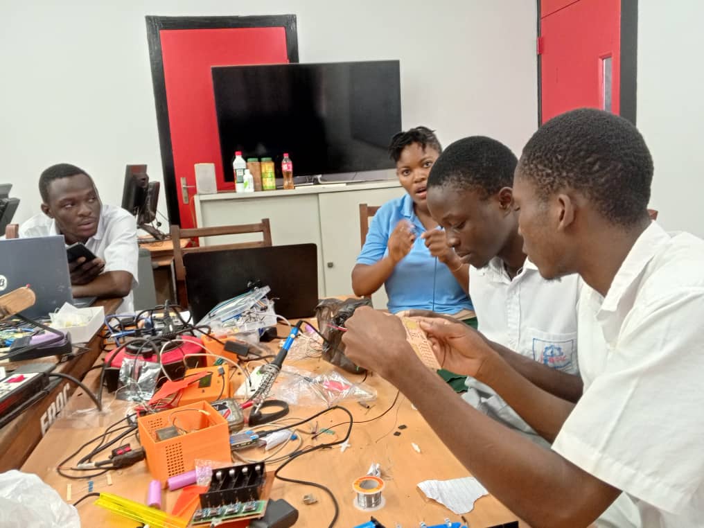 |
|---|---|
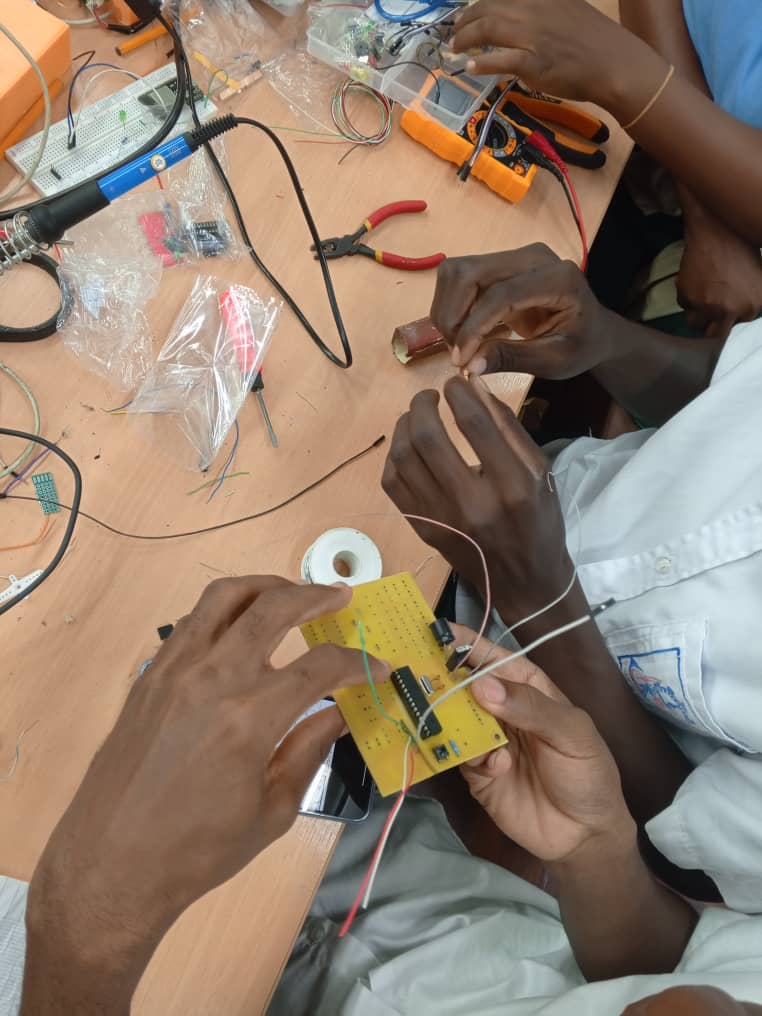 | 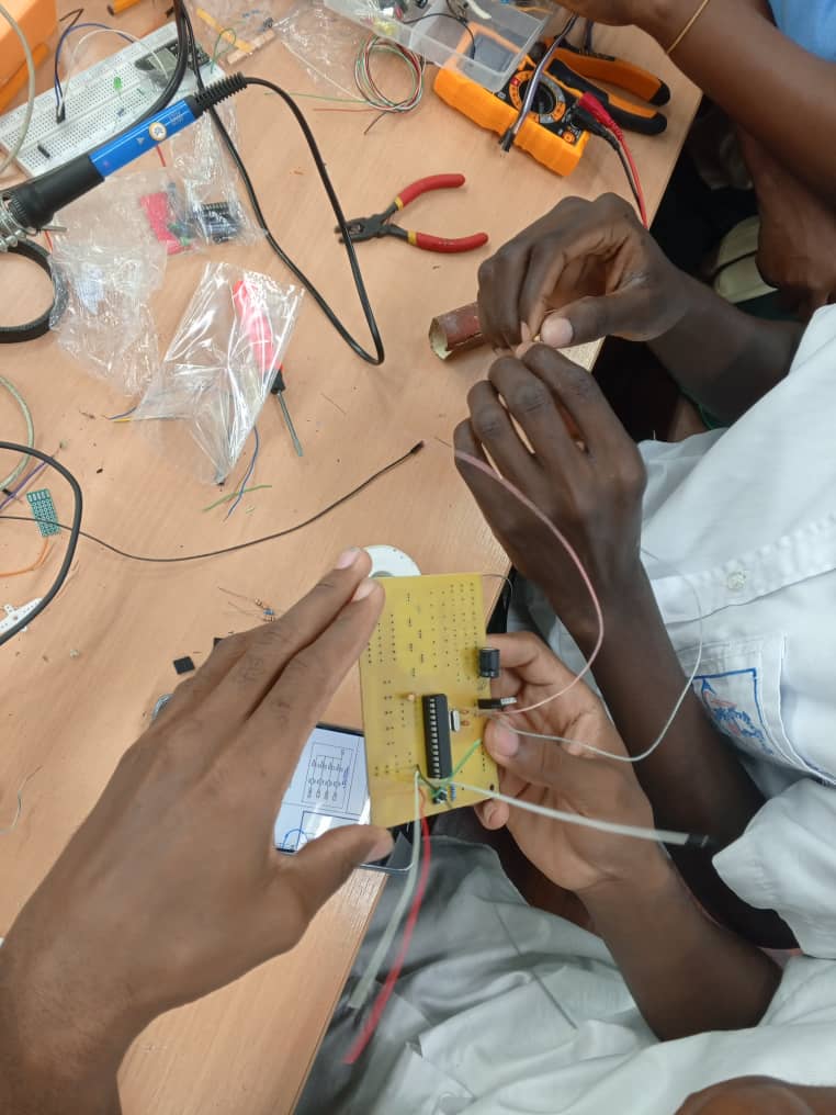 |
Videos
Section titled “Videos”3D Modeling & Enclosure Design
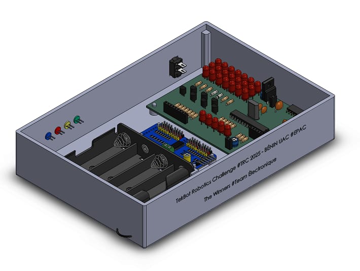
Section titled “3D Modeling & Enclosure Design”The enclosure was designed in Fusion 360 and 3D printed to house all the components.
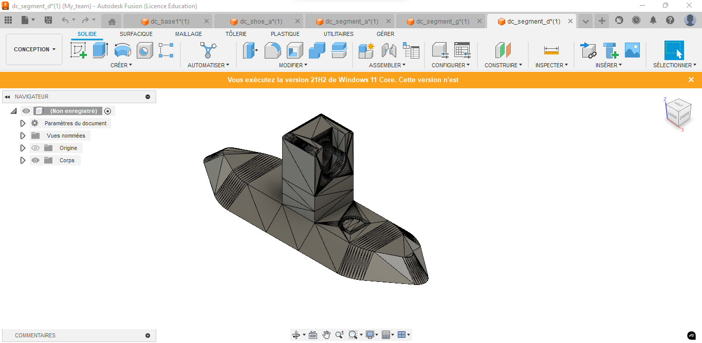 | 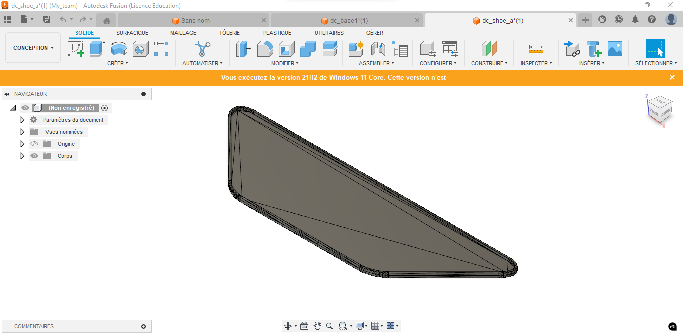 |
|---|---|
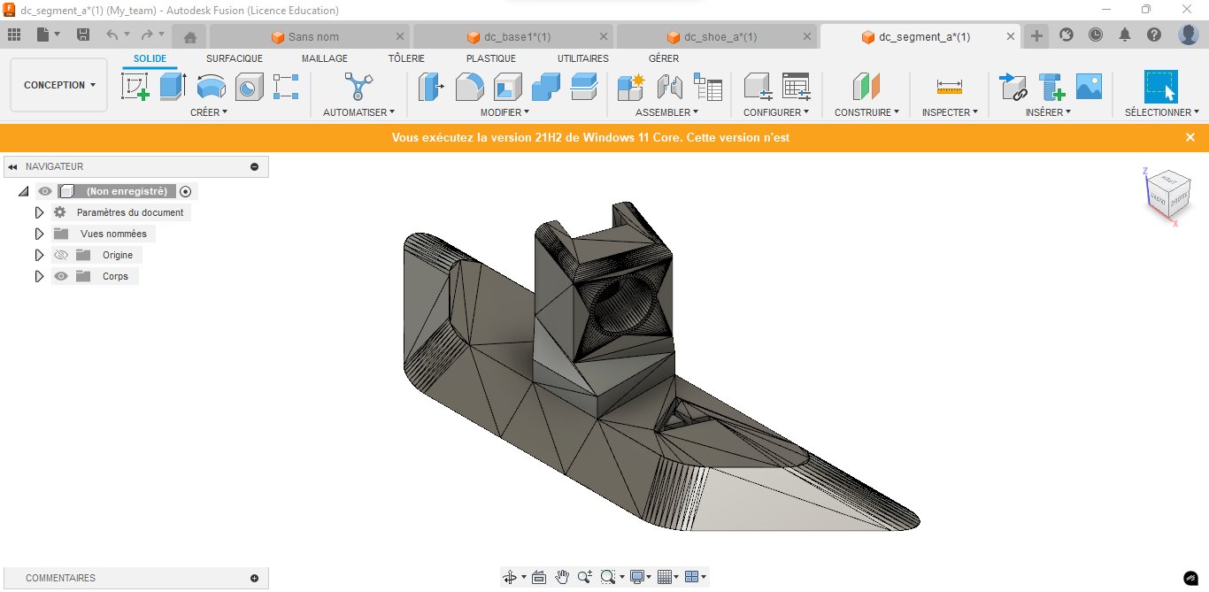 | 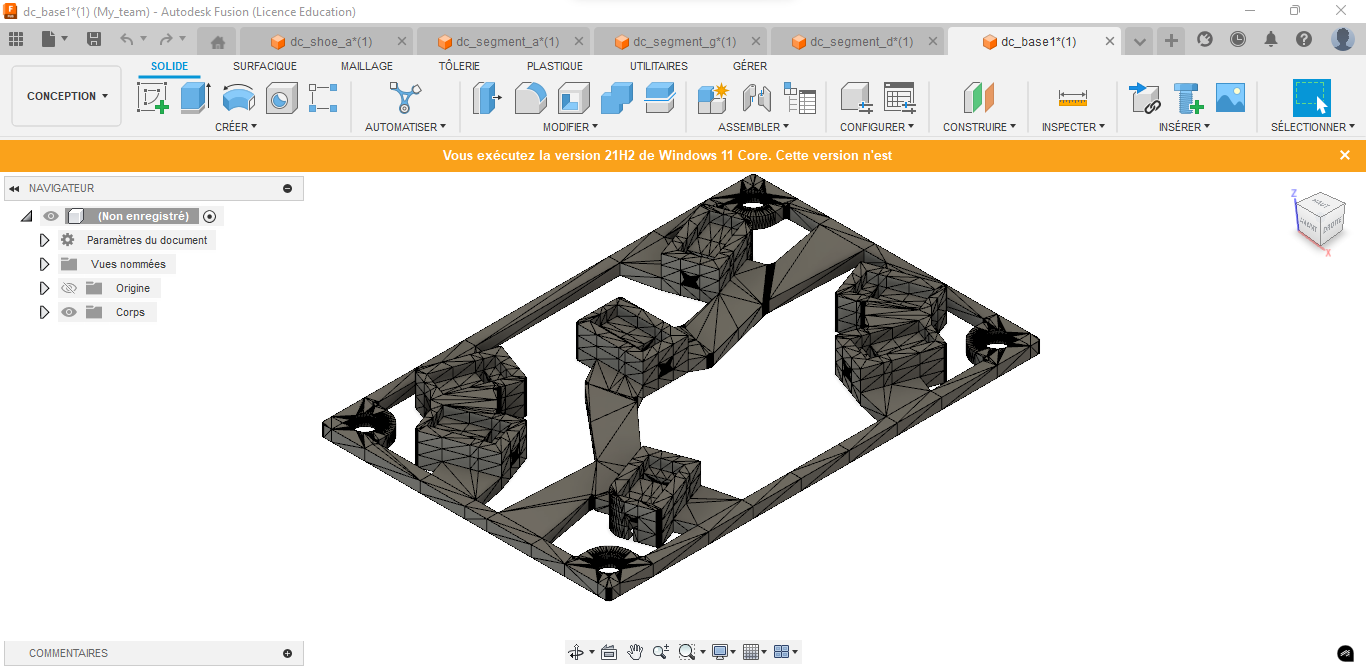 |
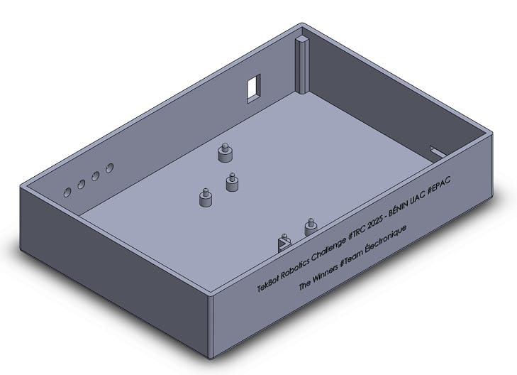 |  |
|---|---|
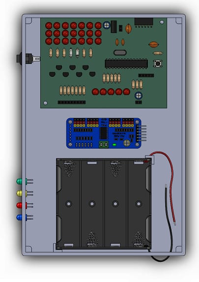 | 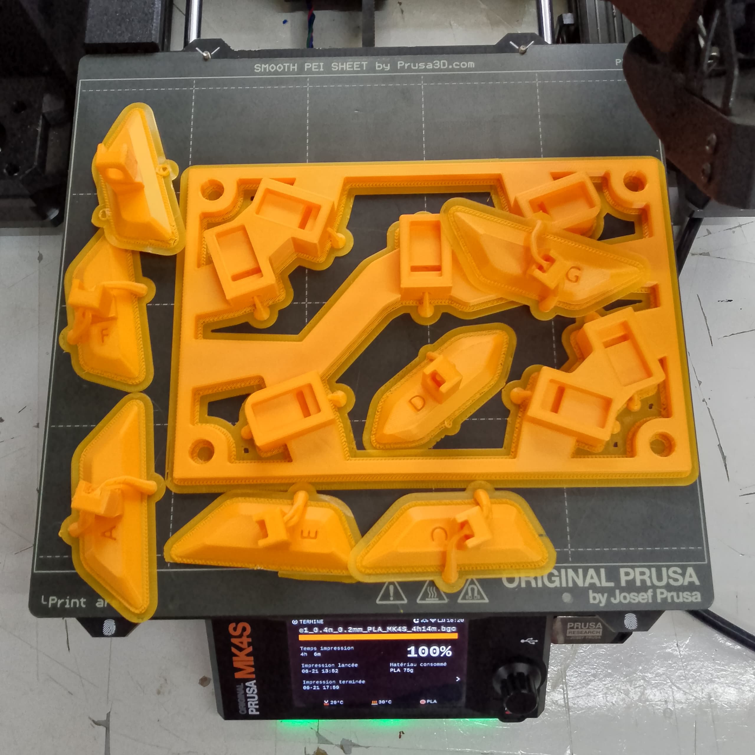 |