Test 3
Dieser Inhalt ist noch nicht in deiner Sprache verfügbar.
title: Electronic description: Documentation of test final.
3rd Test
Section titled “3rd Test”Objective
Section titled “Objective”The advanced level Test 3 consists of modeling a complex part that will be validated by achieving the appropriate mass.
Material specifications:
- Material: 1060 Alloy Aluminum
- Density: 2700 Kg/m³
Summary
Section titled “Summary”This part was mainly created using the following features:
- Extruded boss
- Extruded cut
Mass Table
Section titled “Mass Table”| Configuration | Mass (g) |
|---|---|
| (a) A = 193 mm; B = 88 mm; W = B/2 mm; X = A/4 mm; Y = B+5.5 mm; Z = B+15mm | 1400.64 |
| (b) A = 205 mm; B = 100mm; W = B/2 mm; X = A/4 mm; Y =B+5.5 mm; Z = B+15 mm | 1651.39 |
| (c) A = 210 mm; B = 105 mm; W = B/2 mm; X = A/4 mm; Y = B+5.5 mm; Z = B+15mm | 1760.41 |
Files available for download
Section titled “Files available for download”Download the modeling files by clicking by following these links :
-
Case 1 : SolidWorks File - case1
-
Case 2 : SolidWorks File - case2
-
Case 2 : SolidWorks File - case3
Part Creation Process
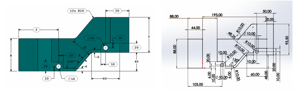
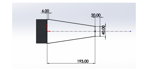
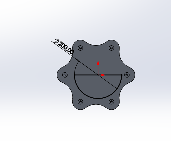
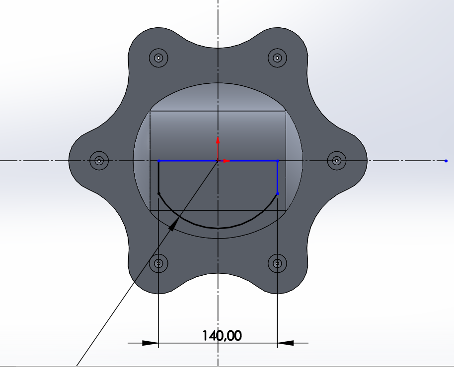
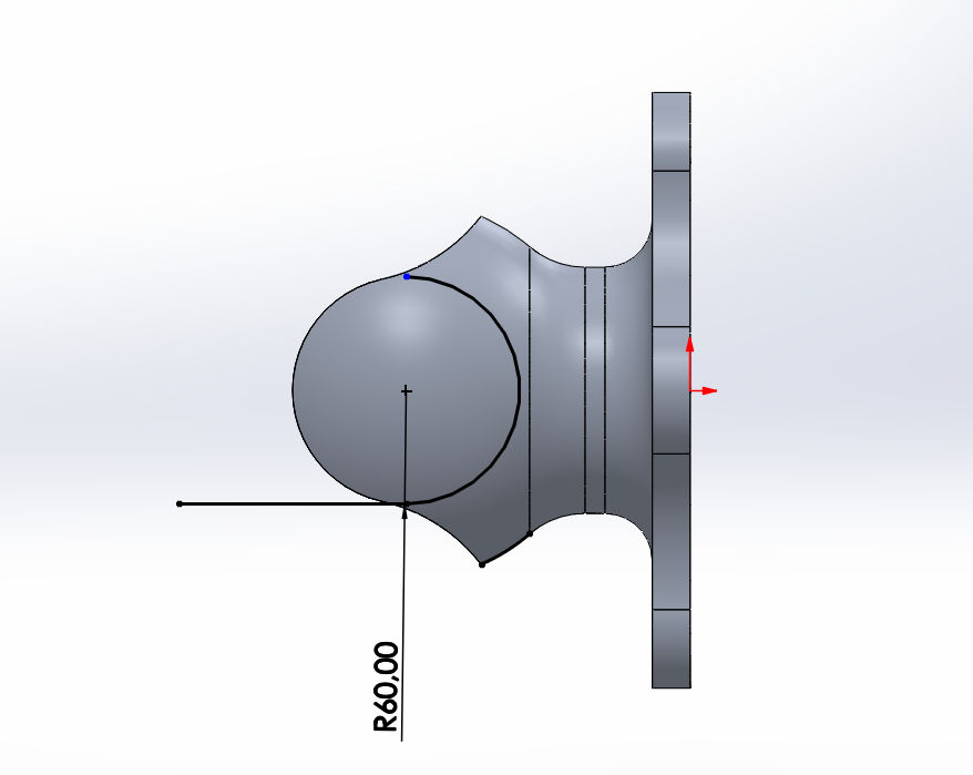
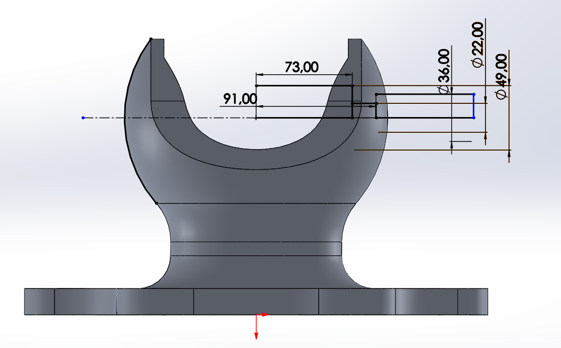
Section titled “Part Creation Process”Step 1: Initial Sketch
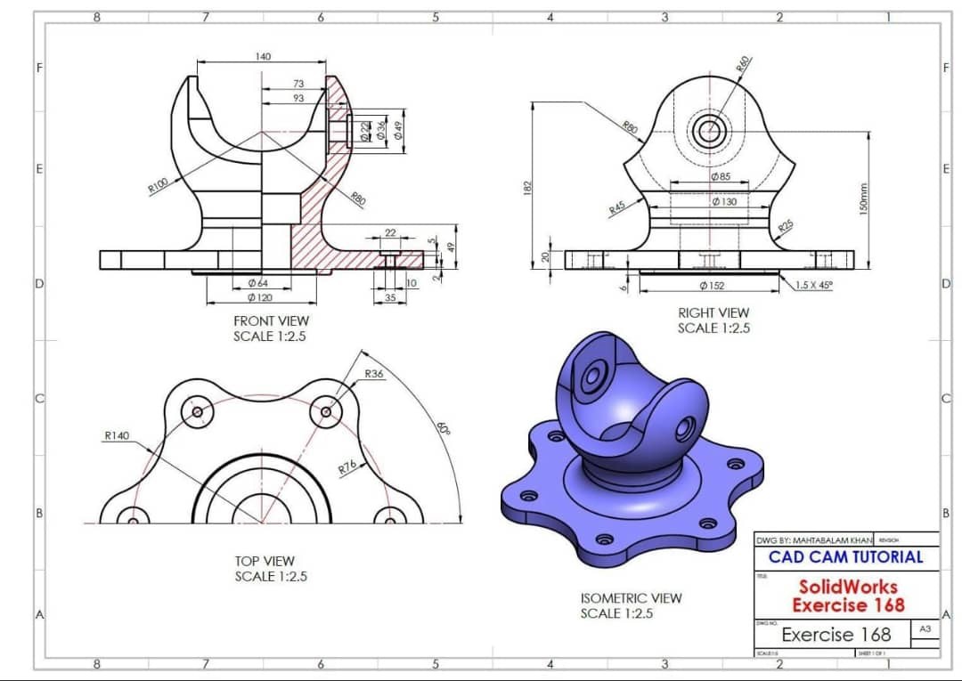
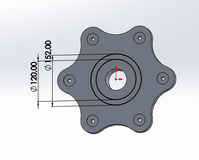
Section titled “Step 1: Initial Sketch”On the front plane, draw the following view while respecting the dimensions and angles.
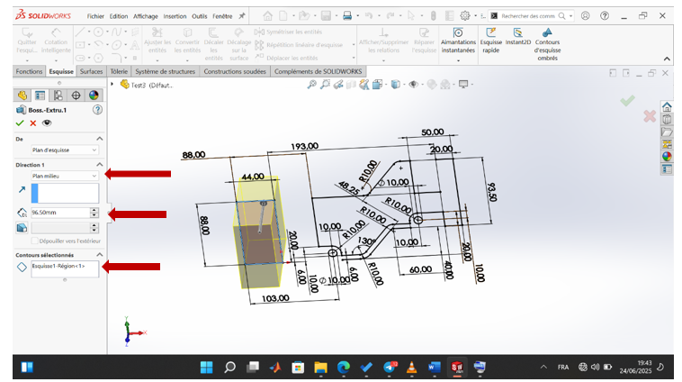
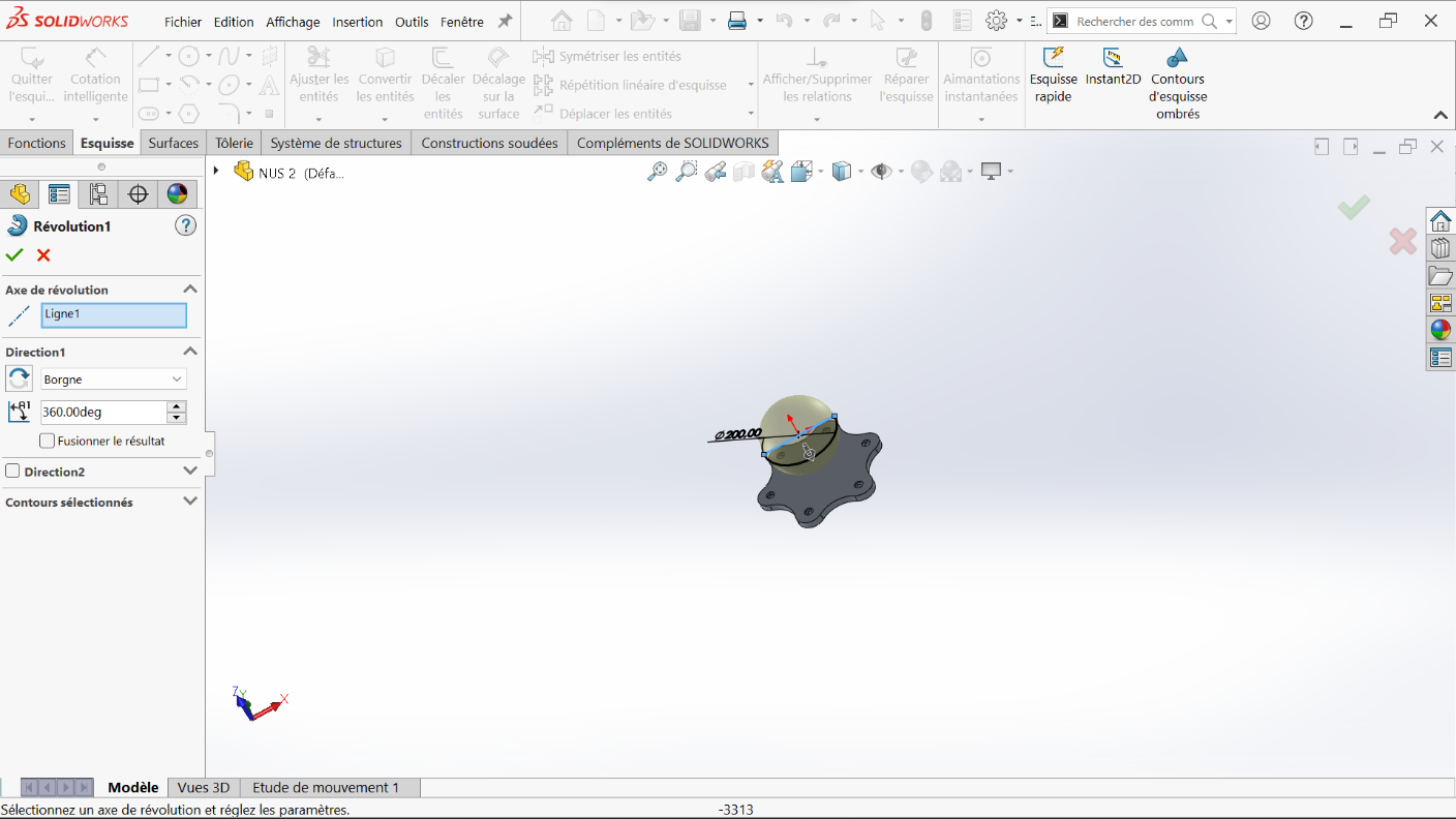
Step 2: Base Extrusion
Section titled “Step 2: Base Extrusion”Use the extruded boss feature and extrude the selected region by 96.5 mm using the mid-plane option.
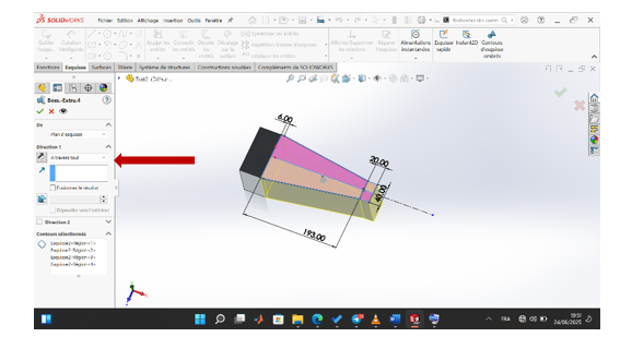
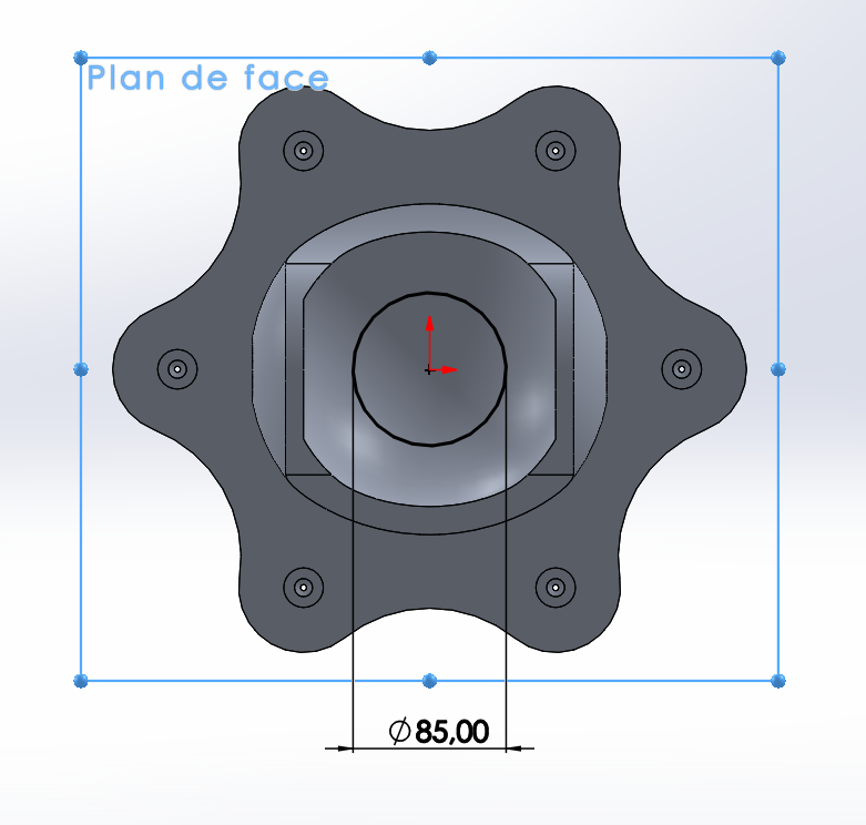
Step 3: Trapezoid Shape
Section titled “Step 3: Trapezoid Shape”On the top plane, make the following sketch with a 6 mm offset to get the trapezoid shape.
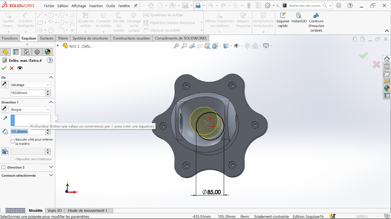
Step 4: Through Extrusion
Section titled “Step 4: Through Extrusion”Make a through all extruded boss.
Step 5: Material Removal Series
Section titled “Step 5: Material Removal Series”Proceed with a series of extruded cuts.
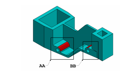
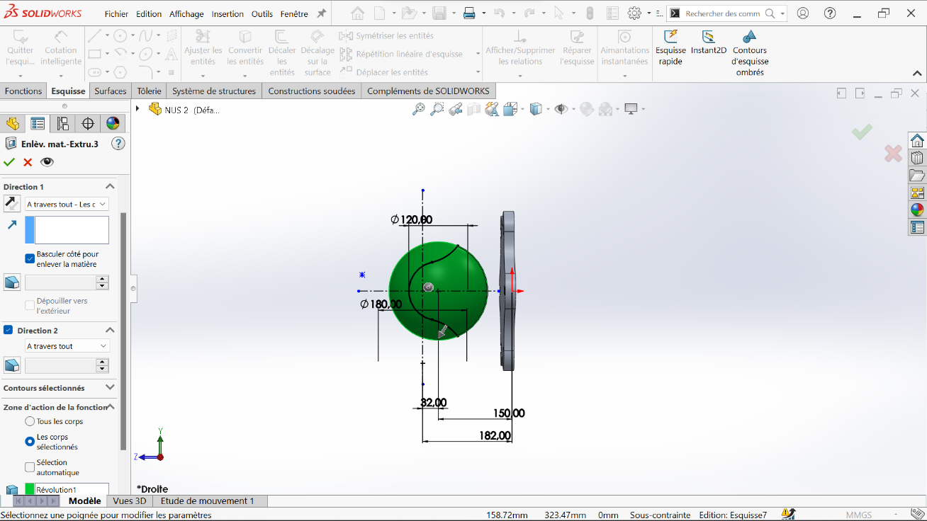
Step 6: First Cut
Section titled “Step 6: First Cut”Make a through all extruded cut from the sketch.
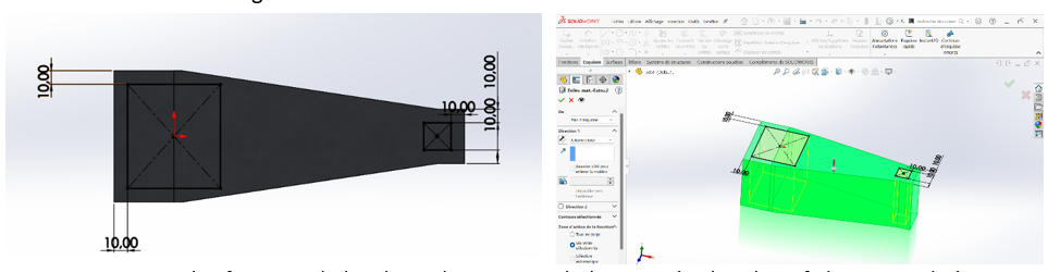
Step 7: Bilateral Cuts
Section titled “Step 7: Bilateral Cuts”Using the first initial sketch, make an extruded cut on both sides of the region, leaving a 5 mm gap between them. Each cut is made with a 2.5 mm offset.
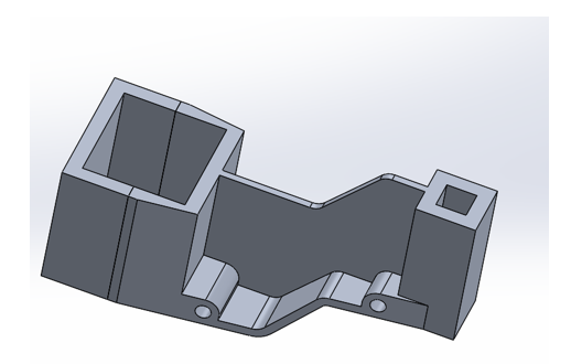
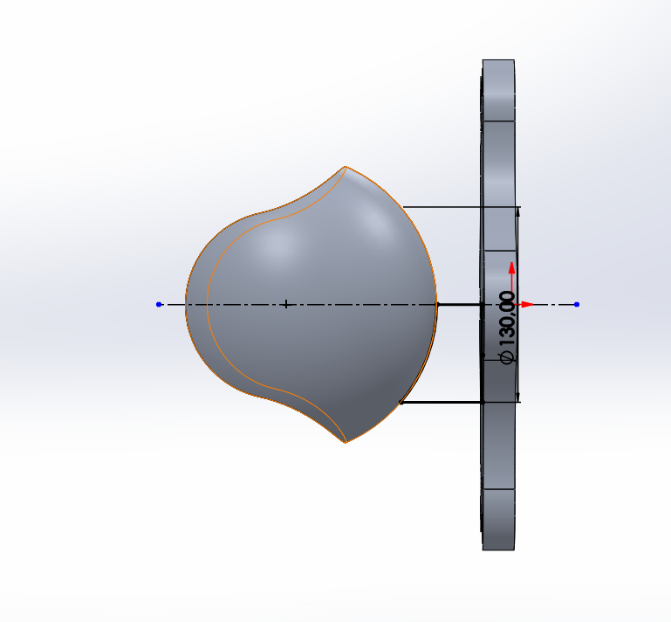
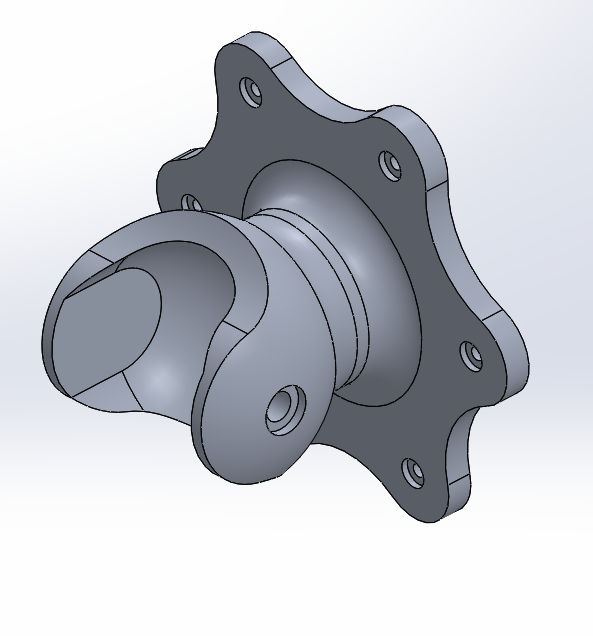
Step 8: Intermediate Result
Section titled “Step 8: Intermediate Result”After this operation, we obtain an intermediate part form.
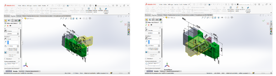
Step 9: Additional Material Removal
Section titled “Step 9: Additional Material Removal”Continue with material removals for the region of sketch 1 (the first sketch).
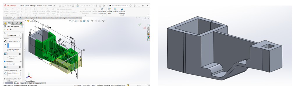
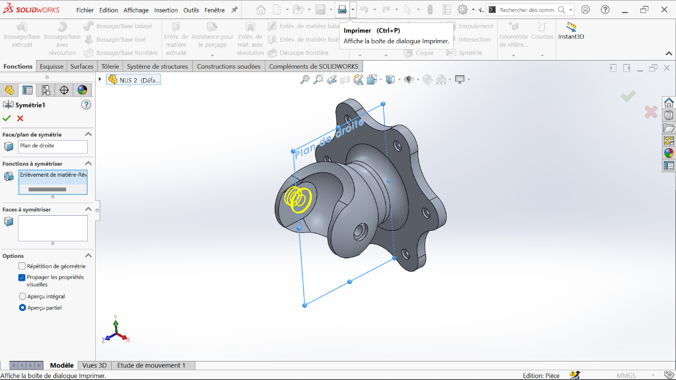
Step 10: Mid-plane Boss
Section titled “Step 10: Mid-plane Boss”Still using the first sketch, create a 5 mm extruded boss with the mid-plane option.
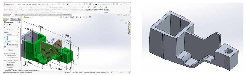
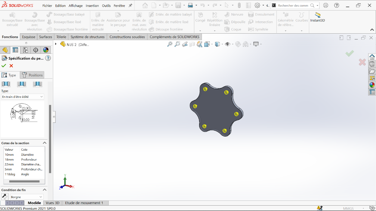
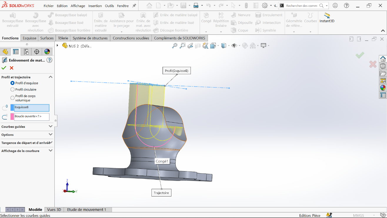
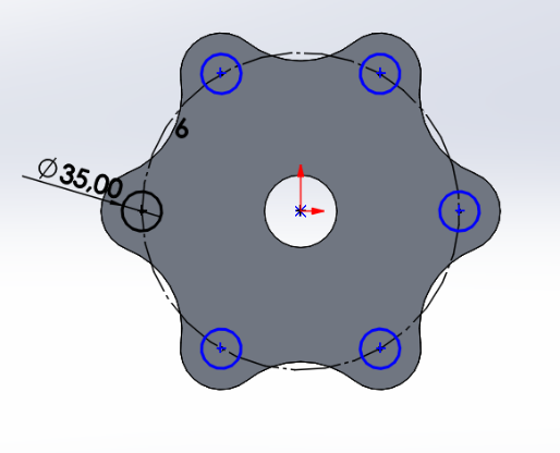
Step 11: Final Features
Section titled “Step 11: Final Features”By making an extruded boss from the sketch on the top plane and extruded cuts for the 10 mm holes, we obtain the penultimate part.
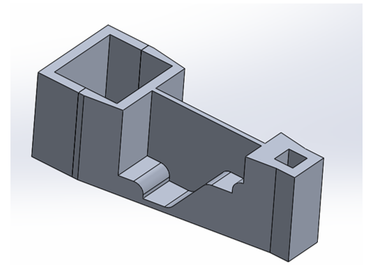
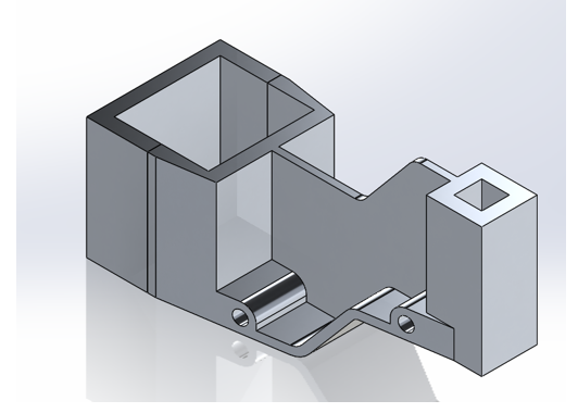
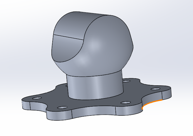
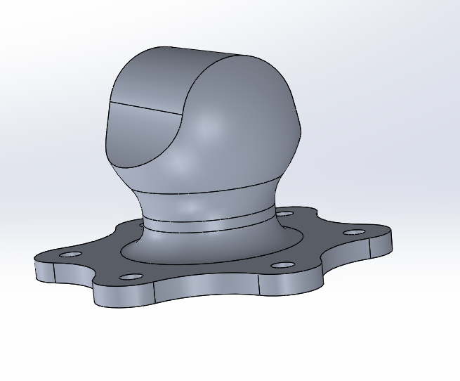
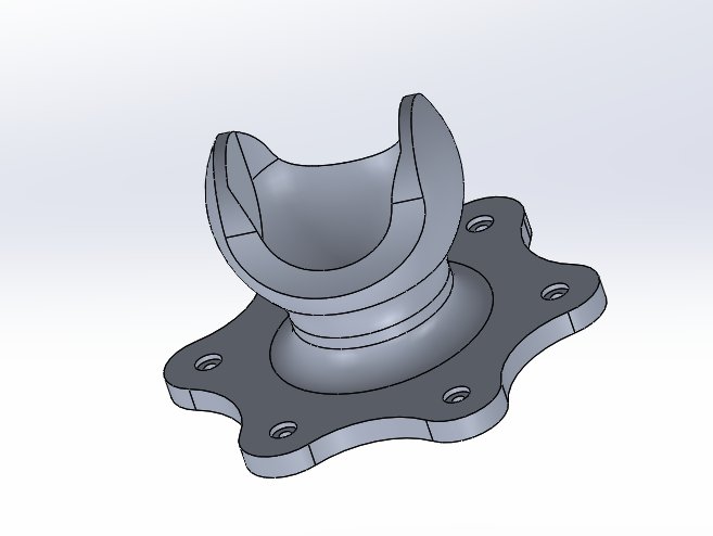
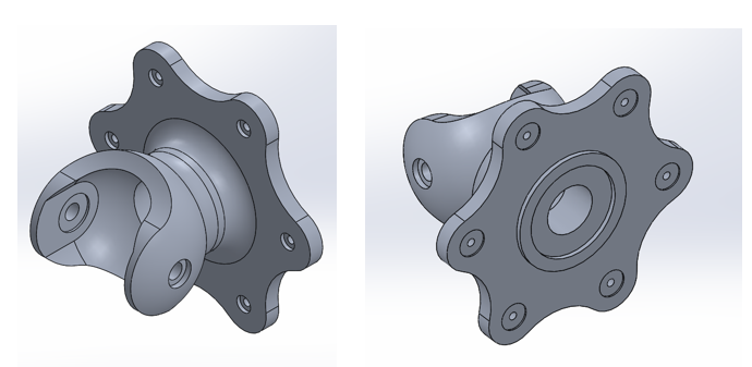
Step 12: Final Part
Section titled “Step 12: Final Part”Apply the material and the desired display mode. This gives us the final Test 3 part.
Variable Dimension System
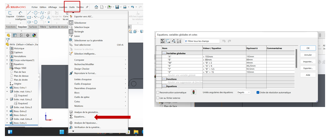
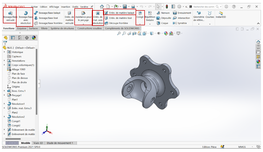
Section titled “Variable Dimension System”Step 13: Global Variables Setup
Section titled “Step 13: Global Variables Setup”For this test, dimensions A, B, Z, Y, X, W must be modified to obtain a new part with a different mass each time. To achieve this:
- Use the equation tool
- Add global variables
- Each time we modify these global variables, the dimensions are adjusted automatically
- This generates a new part configuration
Step 14: Variable Linking Methods
Section titled “Step 14: Variable Linking Methods”When dimensioning to use variables:
Method 1: Use ”=” which allows selection of the variable in question
Method 2: Link the dimension already placed on the drawing to the global variable already created
Step 15: Multiple Configurations
Section titled “Step 15: Multiple Configurations”At the end of this series of variable modification operations, we obtain 3 different pieces of different masses. The masses of the pieces are designated as configurations a, b, and c.
(a) A = 193 mm; B = 88 mm; W = B/2 mm; X = A/4 mm; Y = B+5.5 mm; Z = B+15mm;
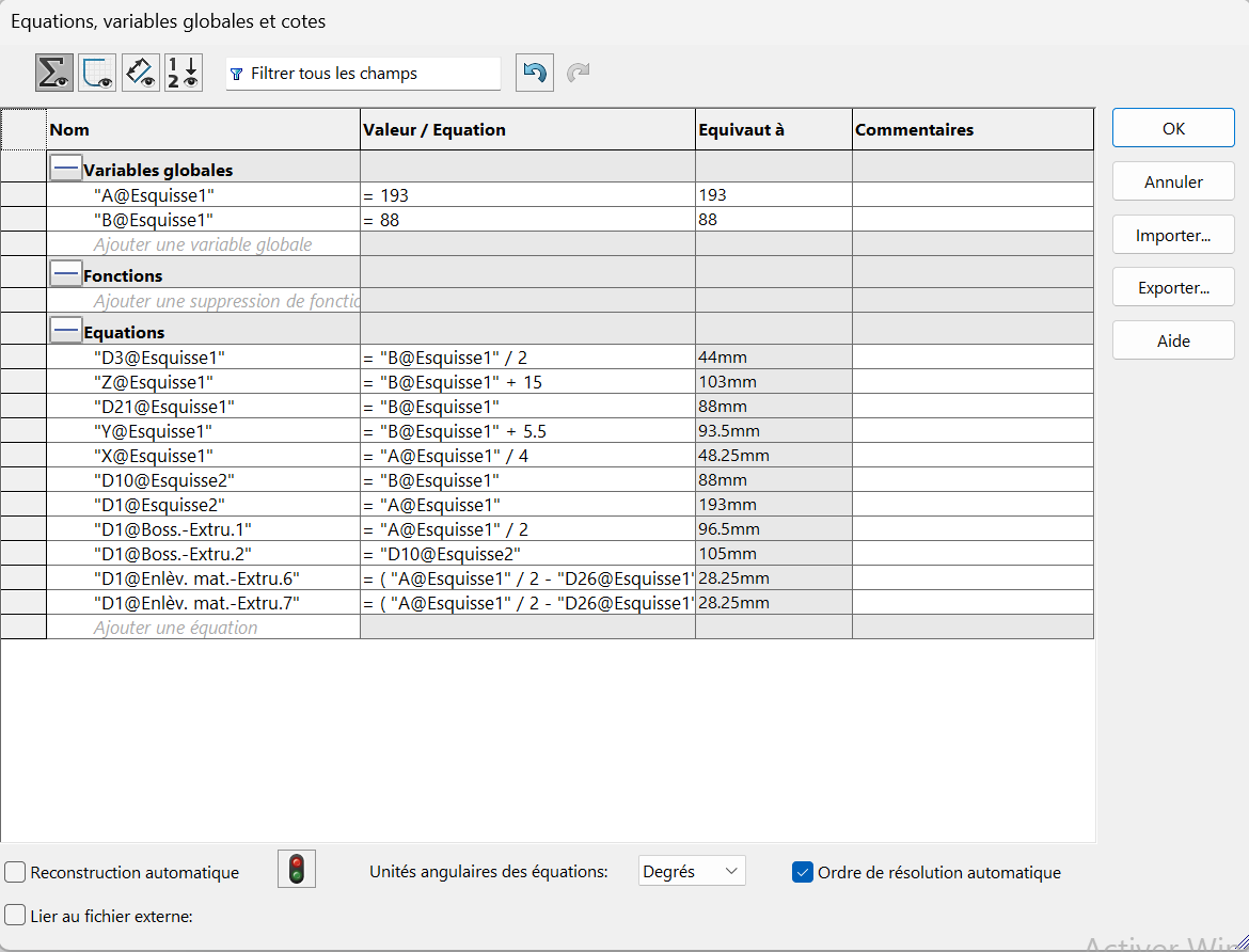
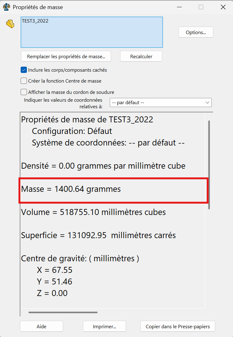
The part mass is : 1400.64 gramms
(b) A = 205 mm; B = 100mm; W = B/2 mm; X = A/4 mm; Y =B+5.5 mm; Z = B+15 mm;
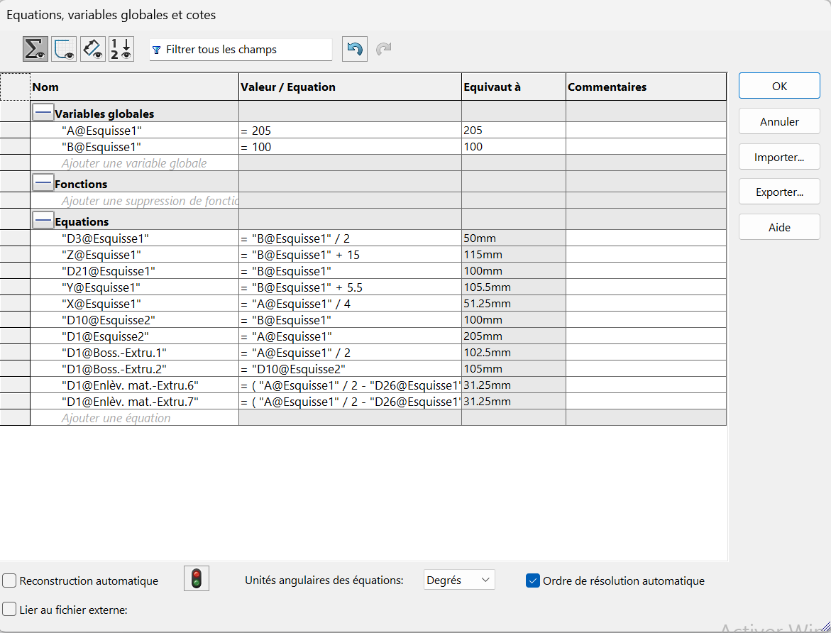
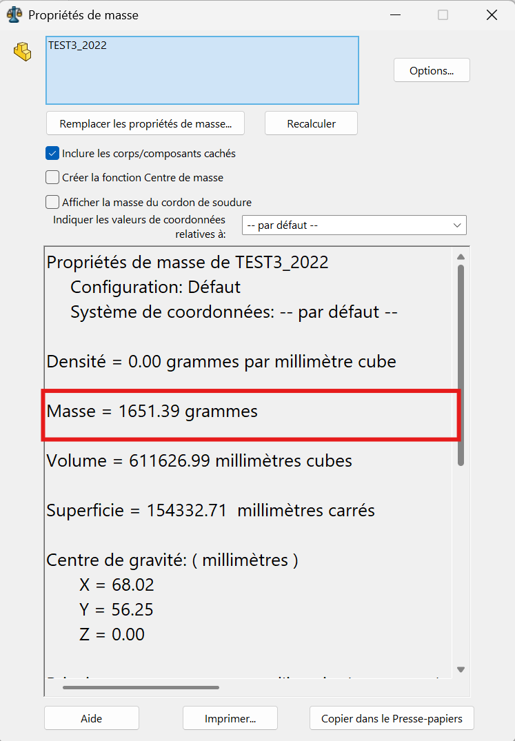
The part mass is : 1651.39 gramms
(c) A = 210 mm; B = 105 mm; W = B/2 mm; X = A/4 mm; Y = B+5.5 mm; Z = B+15mm;
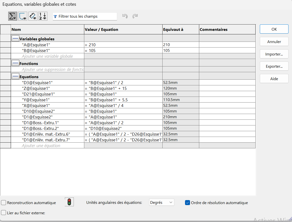
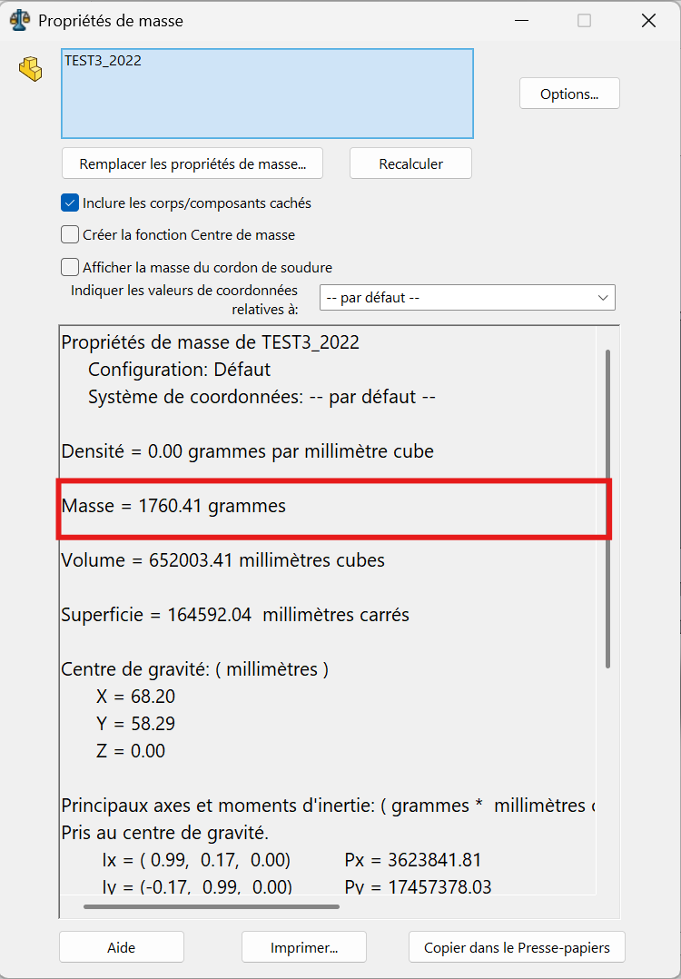
The part mass is : 1760.41 gramms
Alternative Perspectives
Section titled “Alternative Perspectives”Multiple paths allow for creating the same part. The part in this test can also be created using the following alternative method:
Alternative Method A
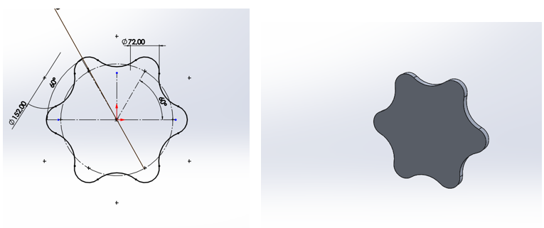
Section titled “Alternative Method A”On the top plane, create the following sketch and make an extruded boss of “B” mm.
Alternative Method B
Section titled “Alternative Method B”On the front plane, make the following sketch and proceed to remove extruded material to obtain the part.
Alternative Method C
Section titled “Alternative Method C”Use global variables or dimension directly on the sketches to have the three requested parts with the desired dimension specifications.
Note: This document references multiple technical drawings and sketches that guide the 3D modeling process. The parametric approach using global variables allows for efficient generation of multiple part variants.
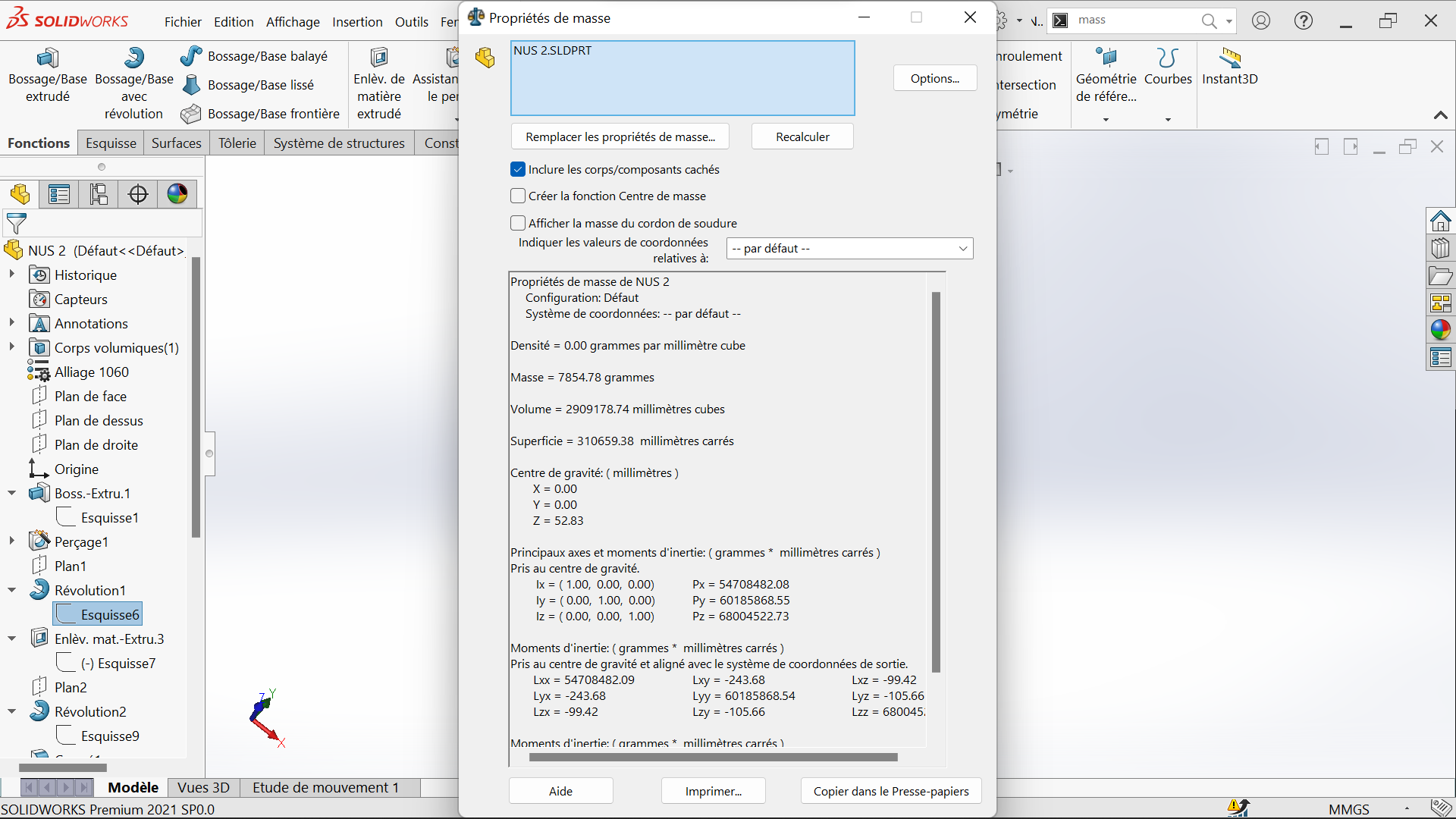
The part mass is 7854,78 gramms
 |  |  |
|---|---|---|
 |  |  |
 |  |  |
 |  |  |
 |  |  |
 |  |  |
|  |  |
 |  |  |