
Test 1
Dieser Inhalt ist noch nicht in deiner Sprache verfügbar.
1rst Test
Section titled “1rst Test”Objectives
Section titled “Objectives”- Produce a batch of parts within a limited time frame while adhering to imposed constraints (materials, dimensions, etc.).
- Comply with a mass tolerance of ±5% for each manufactured part.
- Design sketches incorporating basic geometric shapes:
- Rectangles
- Circles
- Polygons
- Use extrusion and revolution features to model 3D parts based on the sketches.
- Evaluate the mass of each part.
Summary
Section titled “Summary”Modeling files
Section titled “Modeling files”Access the modeling files by clicking here.
Mass Summary of Part
Section titled “Mass Summary of Part”| Part Number | Mass (g) |
|---|---|
| Part 1 | 2850.16 |
| Part 2 | 290.79 |
| Part 3 | 1633.25 |
| Part 4 | 112.37 |
Center of Gravity Analysis – Gripper
Section titled “Center of Gravity Analysis – Gripper”| Configuration | X (mm) | Y (mm) | Z (mm) |
|---|---|---|---|
| Fully Open | -29.15 | 0.16 | 19.86 |
| Fully Closed | -25.78 | 0.06 | 19.86 |
Materials
Section titled “Materials”- Computer
- Internet connection
Execution
Section titled “Execution”Modeling of the First Part
Section titled “Modeling of the First Part”Unit Systems and Material Properties
Section titled “Unit Systems and Material Properties”- Unit System: MMGS (Millimeter, Gram, Second)
- Decimals: 2
- Hole Specification: All holes are through unless otherwise specified
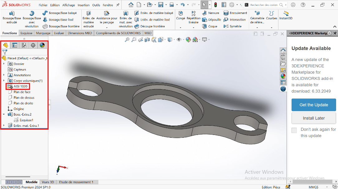
- Material: AISI 1020 Steel
- Density: 0.0079 g/mm³
Process of Obtaining the Part
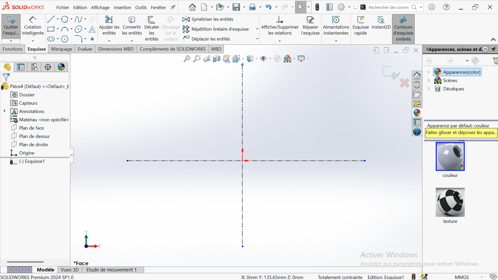
Section titled “Process of Obtaining the Part”—> 1. Workspace Setup
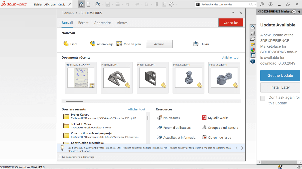
- Launch SolidWorks and select New Part.
- Click on Piece to start modeling a new piece.
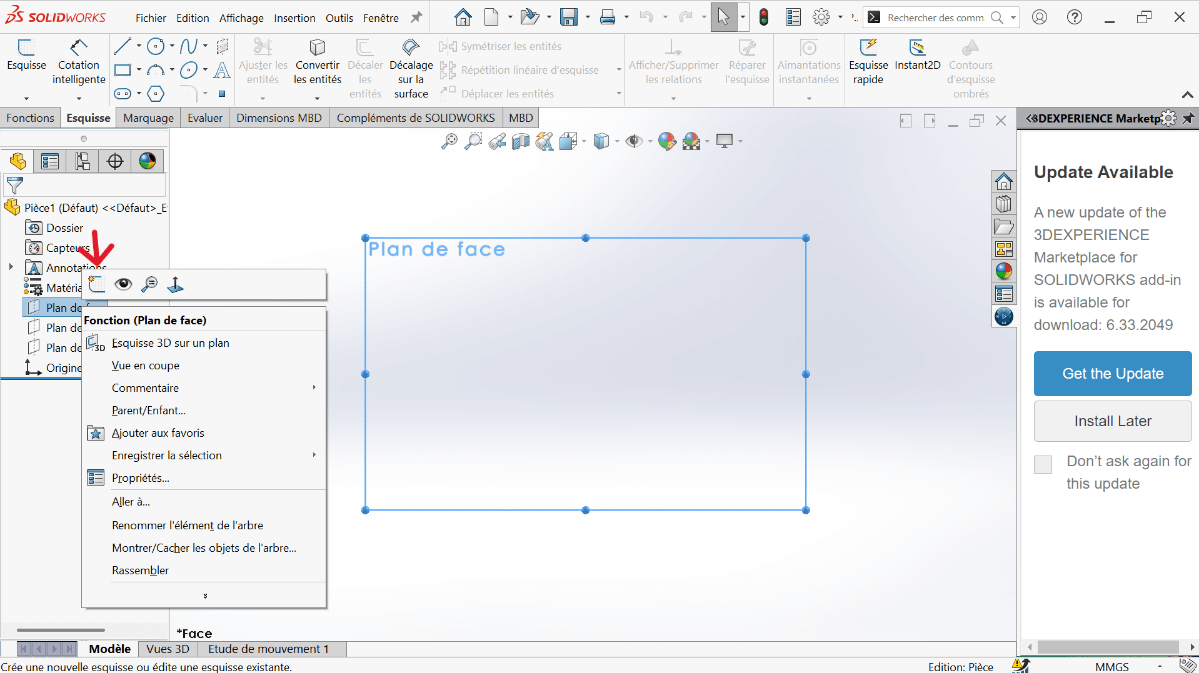
- In the design tree, right-click the Front Plane and choose Edit Sketch.

- Set the unit system to MMGS (Millimeter, Gram, Second).
- Ensure decimals are set to 2.
- Assume all holes are through unless stated otherwise.
- Assign material as AISI 1020 Steel with a density of 0.0079 g/mm³.
—> 2. Sketching the Base Profile
---> a. Create Centerlines
- Click on the Line function.
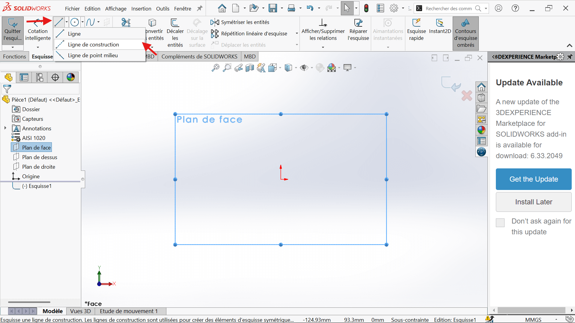
- Select the Horizontal Constraint and For Construction in the properties.
- Position the start and end points, ensuring alignment with the reference frame.
- Click Validate to confirm.
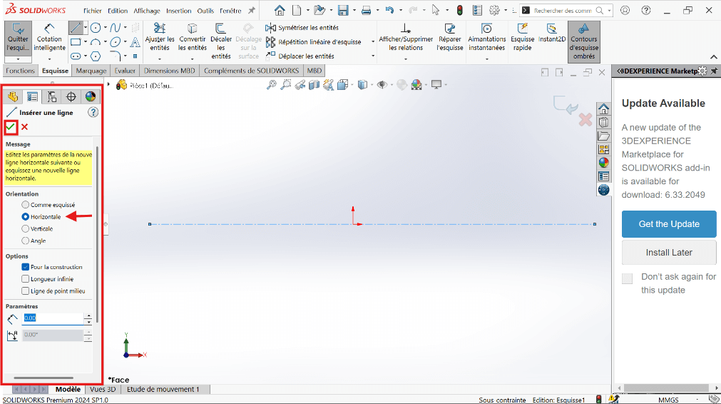
- Click again on the Vertical Constraint to draw the vertical axis, ensuring alignment with the reference frame.
- Click Validate to confirm.
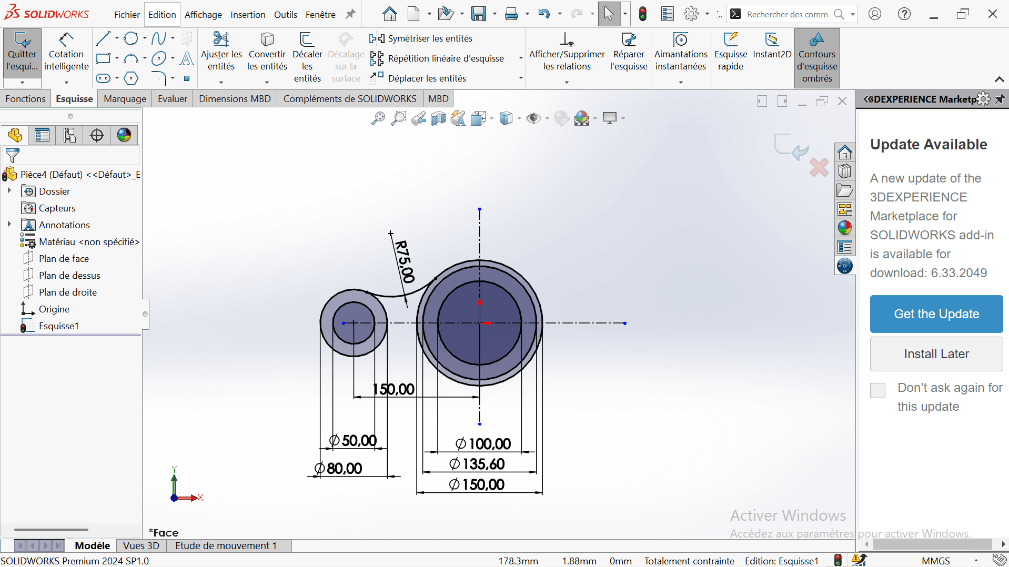
---> b. Draw Concentric Circles
- In the top ribbon, click on “Circle”.
- Click on the intersection point of the two axes (center of the circle).
- Stretch the circle to any size for now.
- Enter the circle radius in the properties panel on the left.
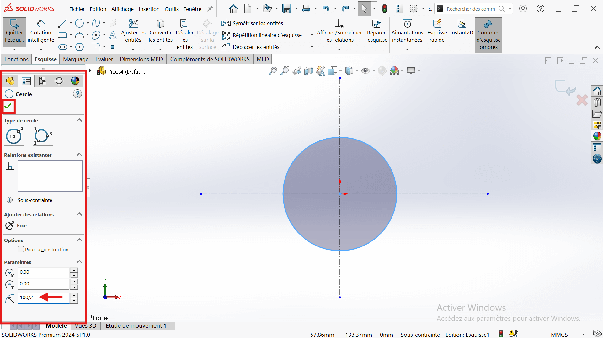
- Select the “Smart Dimension” tool.
- Click on the edge of the circle → a diameter dimension will appear.
- Enter the value 100 mm (since the radius is 50 mm, the diameter is 100 mm).
- Click Validate to confirm.
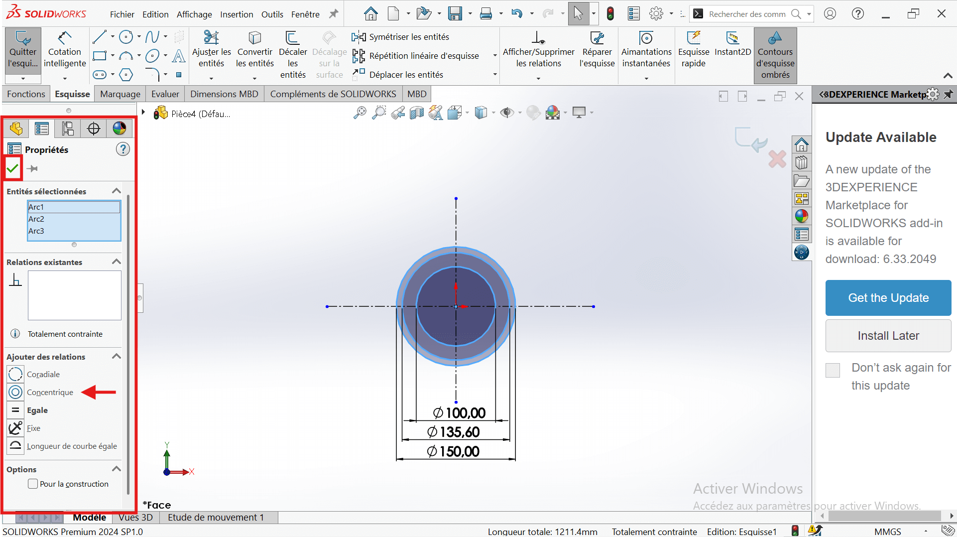
- Draw two other circles centered on the origin:
- Diameter 135.6 mm
- Diameter 150 mm
- Apply concentricity constraints to ensure a common center.
---> c. Add Offset Circle
- Create a new circle on the horizontal axis, offset from the origin.
- Set its diameter to 80 mm (radius = 40 mm).
- Use Smart Dimension to set the center-to-center distance from the 150 mm circle to 150 mm.
---> d. Add Additional Circle
- Draw another circle with a diameter of 50 mm, concentric with the 80 mm circle.

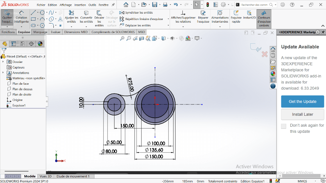
—> 3. Creating Fillet and Cutout
---> a. Create Tangent Arc
- Use the Perimeter Circle to draw a circle tangent to the 150 mm and 80 mm circles.
- Set the appropriate diameter to represent a 75 mm fillet.
- Use the Trim Entities tool to remove excess lines, forming a closed contour.
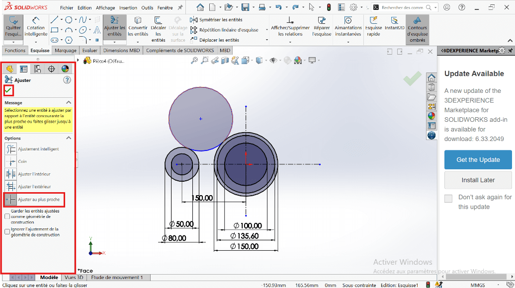
---> b. Offset the Arc
- Select the arc and apply a 10 mm offset using Offset Entities.
- Trim intersecting entities to clean up the sketch.
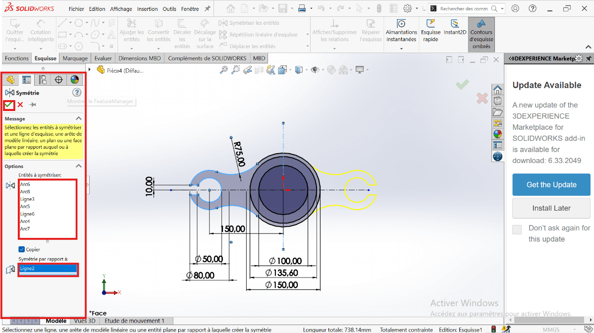
---> c. Mirror the Cutout
- Use Mirror Entities to duplicate the feature across the horizontal axis.
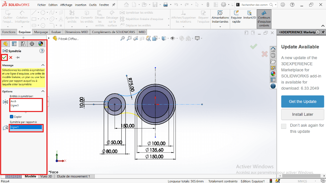
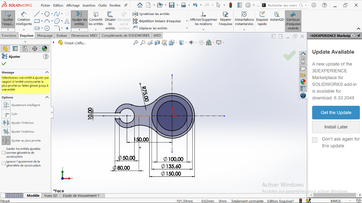
- Then mirror the resulting shapes across the vertical axis for full symmetry.
 .
.
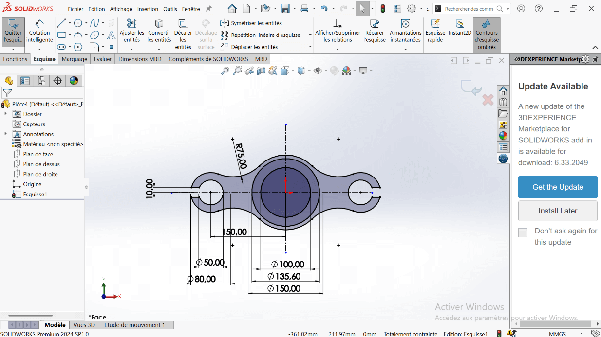
- Ensure the sketch forms a closed loop.
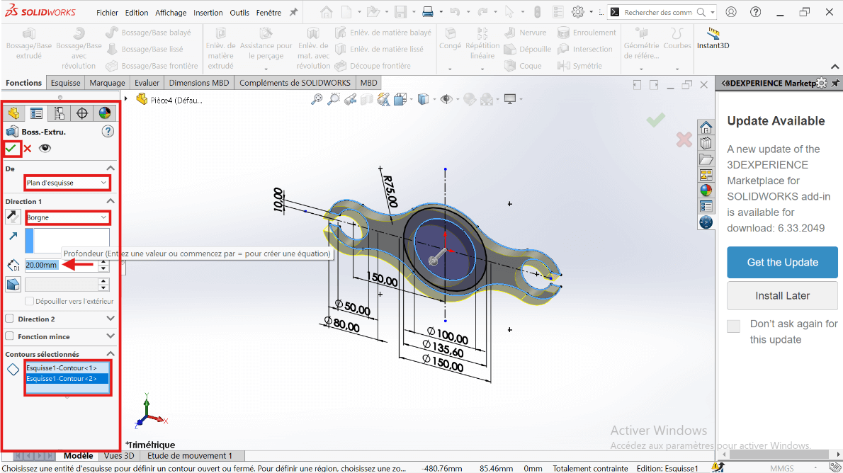
—> Creating the 3D Volume
-
Exit the sketch and switch to the Features tab.
-
Use Extruded Boss/Base:
- Select the entire sketch.
- Choose Blind extrusion with a depth of 20 mm.
- Select only the 100 mm diameter region to extrude the solid part.
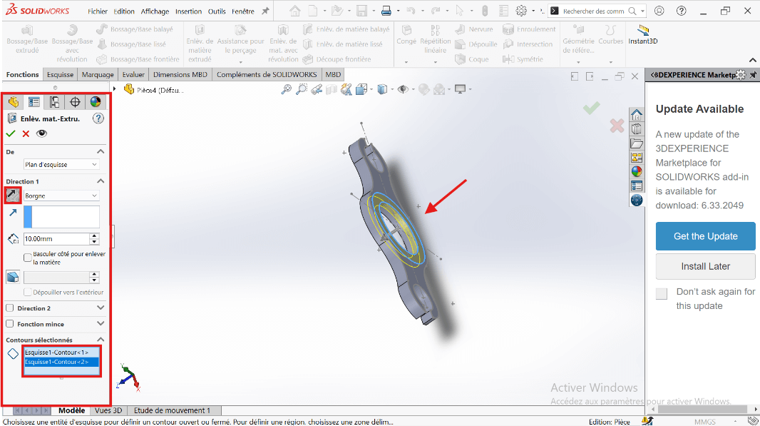
—> 5. Adding the Cut (Counterbore)
- Use Extruded Cut on the same sketch:
- Set cut depth to 10 mm.
- Select the region between 100 mm and 135.6 mm circles as the cut profile.
—> 6. Mass Evaluation
- Type Mass in the search bar.
- Click on Mass Properties.
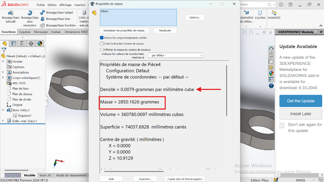
The part mass should be 2850.16 grams.
Modeling of the Second Part
Section titled “Modeling of the Second Part”Unit Systems and Material Properties
Section titled “Unit Systems and Material Properties”- MMGS (Millimeter, Gram, Second)
- Decimals: 2
- Hole Specification: All holes are through unless otherwise specified
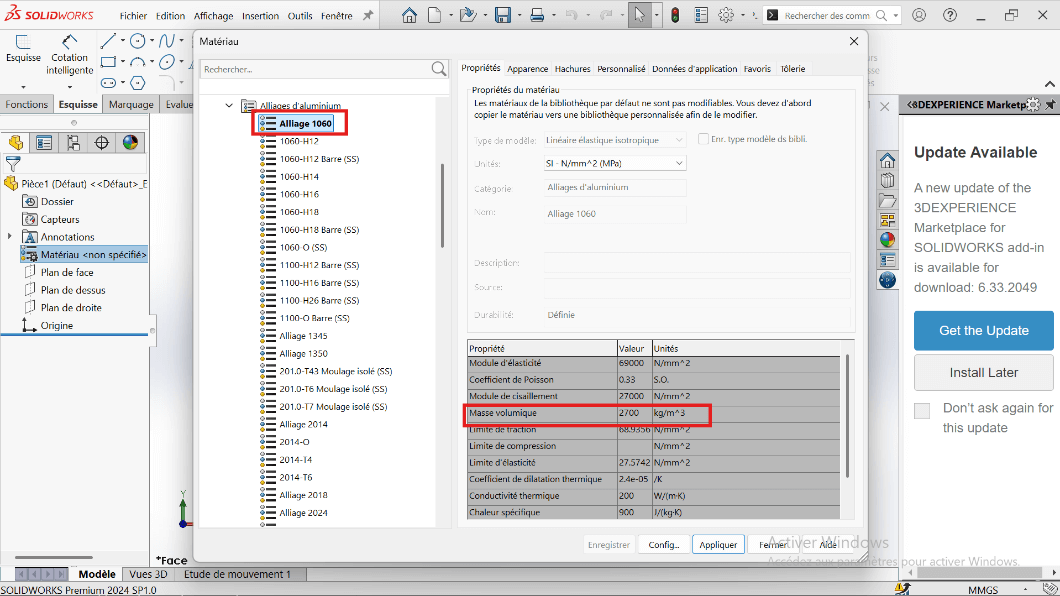
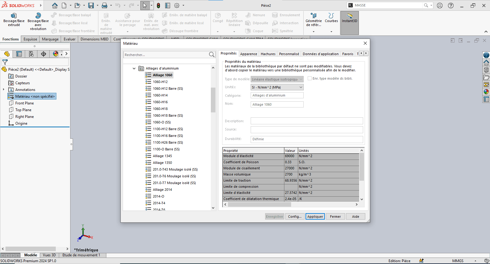
- Material: Aluminum Alloy 1060
- Density: 0.0027 g/mm³
—> 1. Modifying Part 2 Parameters
- Right-click on Material: “Not Specified”.
- Click on Edit Material.
- The Material tab opens.
- Navigate to SolidWorks Materials → Aluminum Alloy → Alloy 1060.
- Click Apply and Close.
—> 2. Preparing the Workspace
- Click on Front Plane.
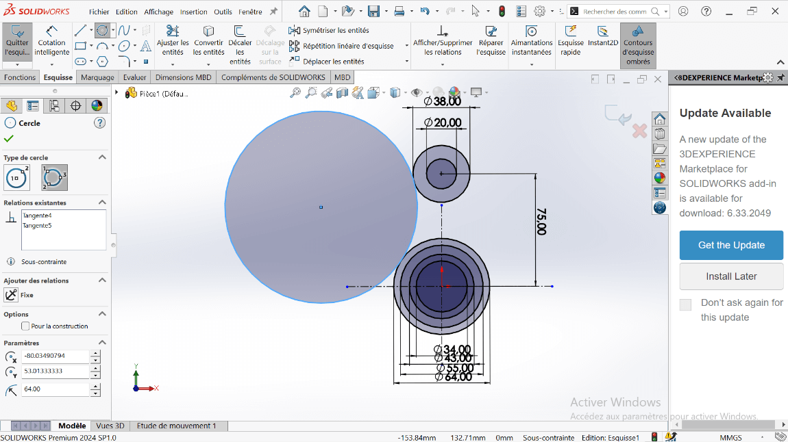
—> 3. Sketch Creation
- Click on the Circle tool and draw concentric circles with diameters 20 mm and 38 mm, centered on the vertical axis.
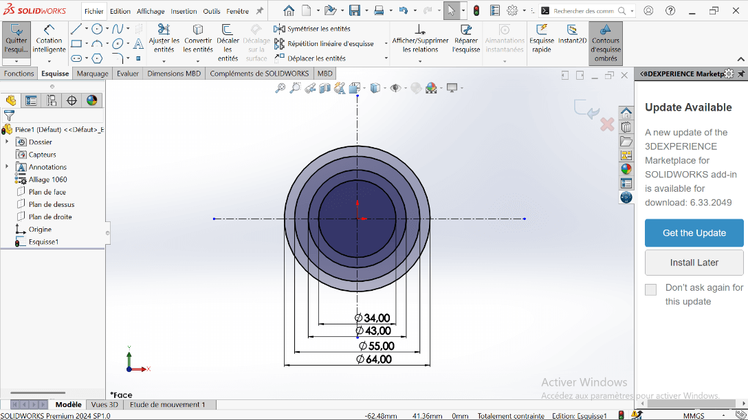
- Click on Smart Dimension:
- Select the 64 mm and 38 mm diameter circles.
- Specify the center distance as 75 mm and validate.
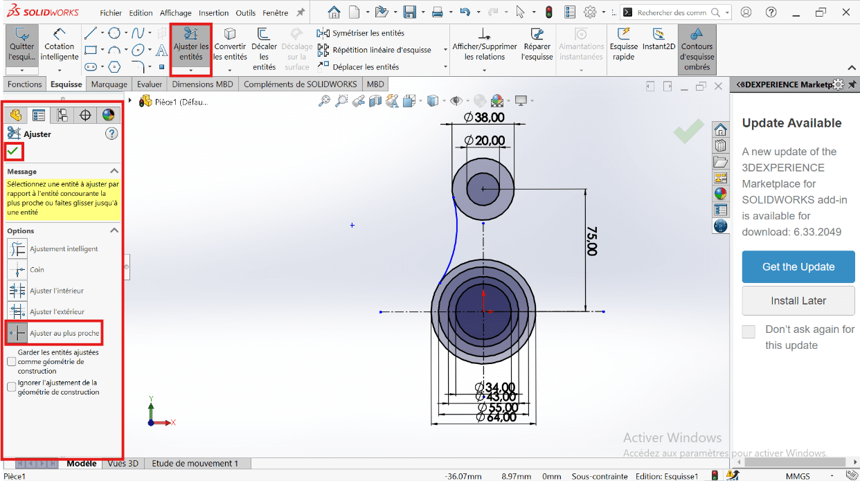
- Right-click on the Circle tool and select Perimeter Circle.
- Select the entities:
- Click on the 64 mm and 38 mm diameter circles.
- Click on an external point (the created circle will be tangent to the selected circles).
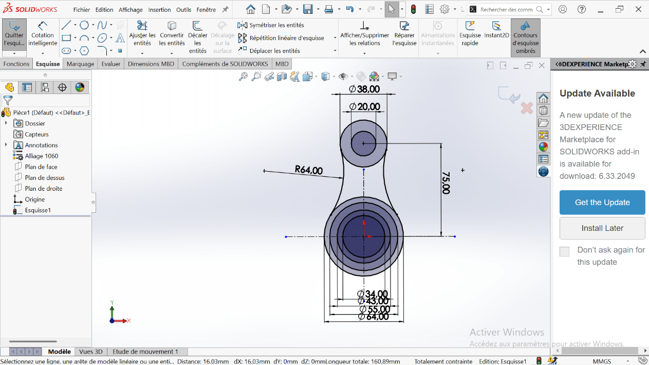
- Specify the fillet radius as R64.
- Click on the Trim Entities tool to remove overlapping sketch parts and create a closed sketch.
- Select the Trim tool properties.
- Click on the entities to remove.
- Apply the dimensioning to the fillet.
- Click on the Symmetry tool.
- Select the entities to symmetrize: R64 fillet.
- Select the symmetry axis: Vertical axis.
—> 3. Creating the Volume
- Click on Features → Extruded Boss/Base.
- Select the entities to extrude.
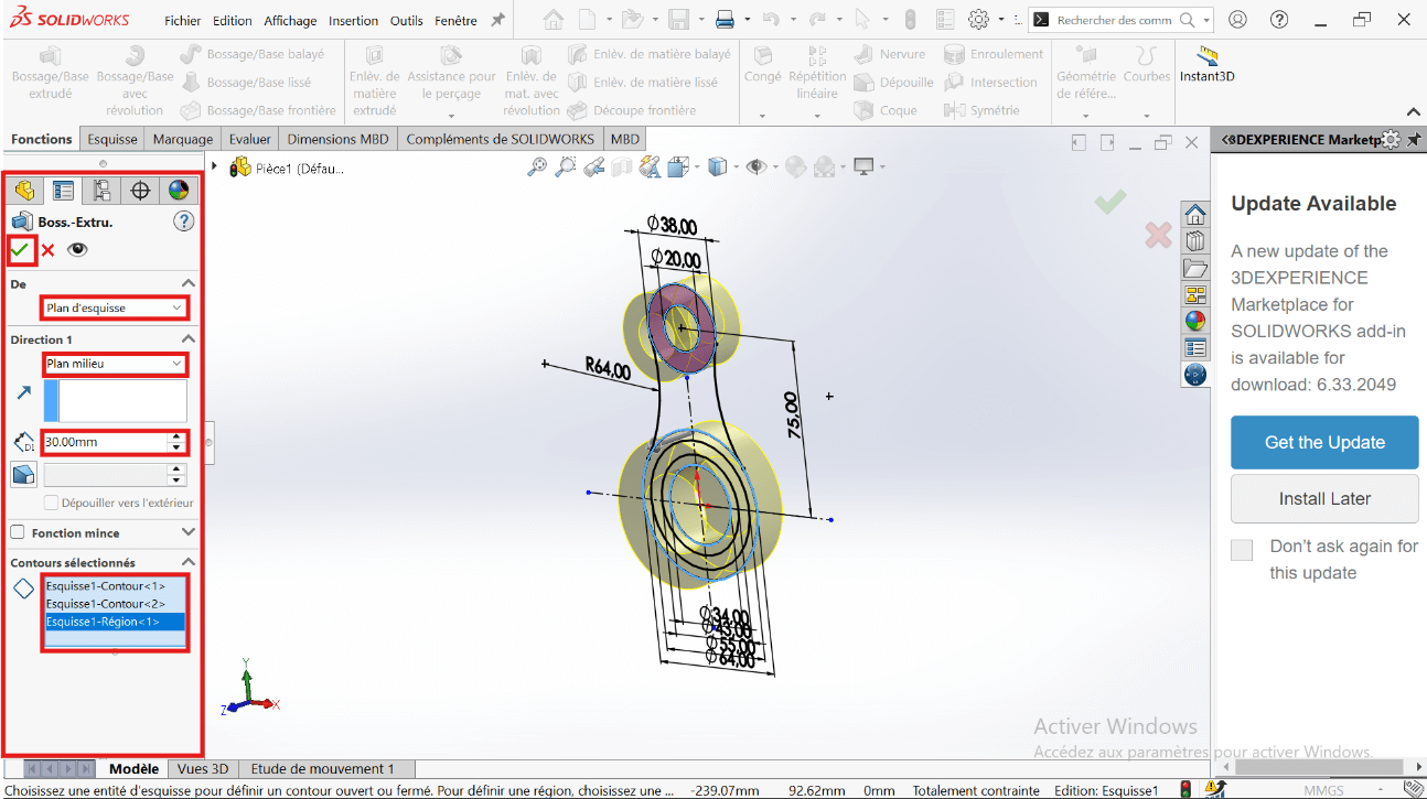
- Click Validate.
- Click on Boss/Base → Sketch.
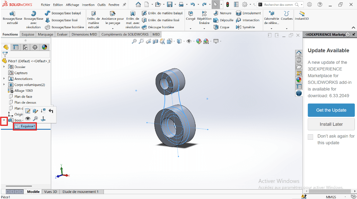
- Click on Features → Extruded Boss/Base.
- Select the entities to extrude.
- Click Validate.
- Click on Boss/Base → Sketch → Extruded Boss/Base.
- Select the entities to extrude: 43 mm and 34 mm diameter circles.
- In the parameters, select Direction 1 and Direction 2.
- Specify the extrusion distances: 15 mm and 30 mm.
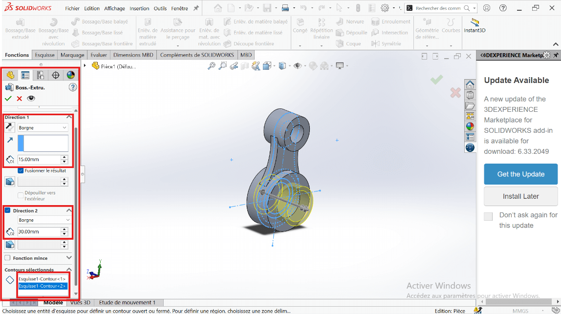
- Click Validate.
- Click on Boss/Base → Sketch → Extruded Cut.
- Select the entities to cut: 43 mm and 55 mm diameter circles.
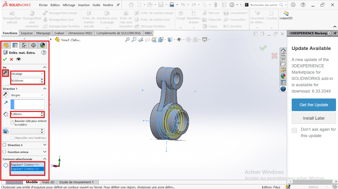
- Click Validate.
—> 6. Mass Properties
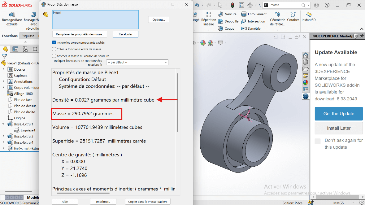
- Mass Calculation: Use the Mass Properties tool to determine the part’s mass.
The part mass is : 290.79 gramms
Modeling of the Third Piece
Section titled “Modeling of the Third Piece”Unit System
Section titled “Unit System”- MMGS (Millimeter, Gram, Second)
- Decimals: 2
- Hole Specification: All holes are through unless otherwise specified
- Material: AISI 1020 Steel
- Density: 0.0079 g/mm³
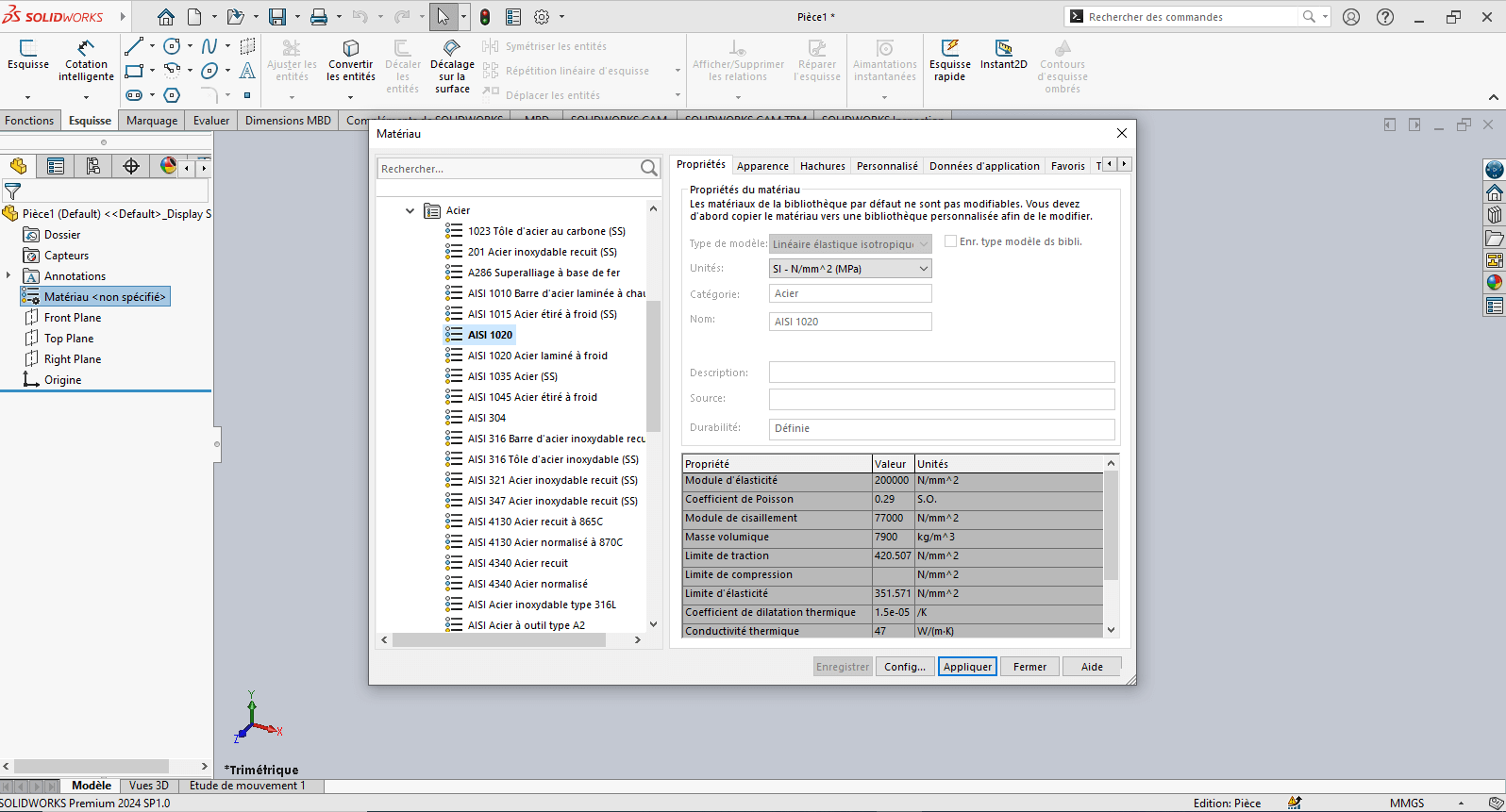
—> 1. Modifying Part 3 Parameters
-
Right-click on Material: “Not Specified”
-
Select Edit Material
-
In the Material tab:
- Browse to SolidWorks Materials > Steel > AISI 1020
- Click Apply, then Close
-
Click on the Front Plane, then select Sketch
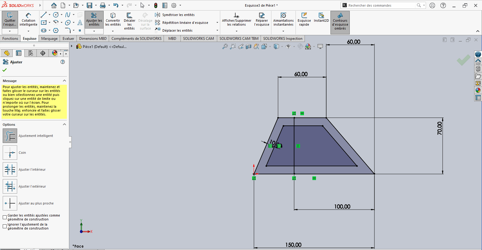
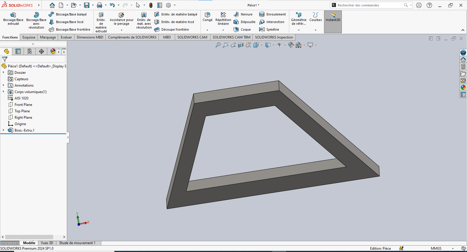
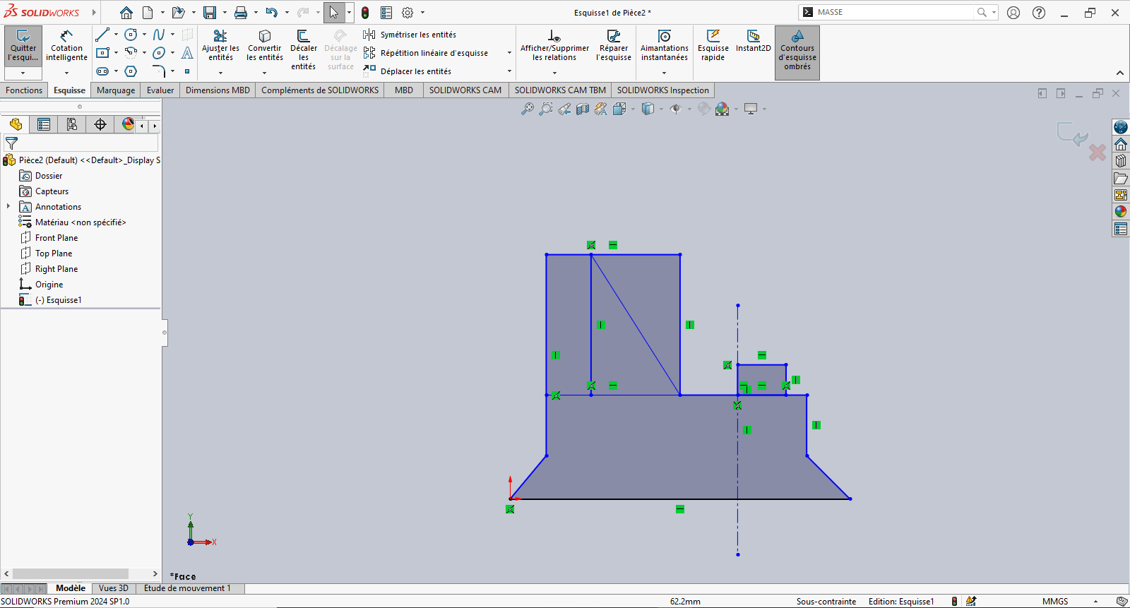
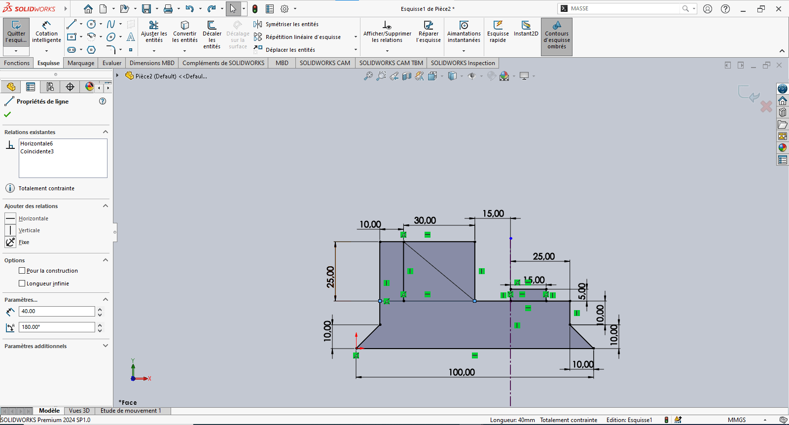
—> 2. Creating the Sketch
- Use the Line tool to draw a trapezoid (initial dimensions can be arbitrary)
- Use Smart Dimensioning to set precise dimensions
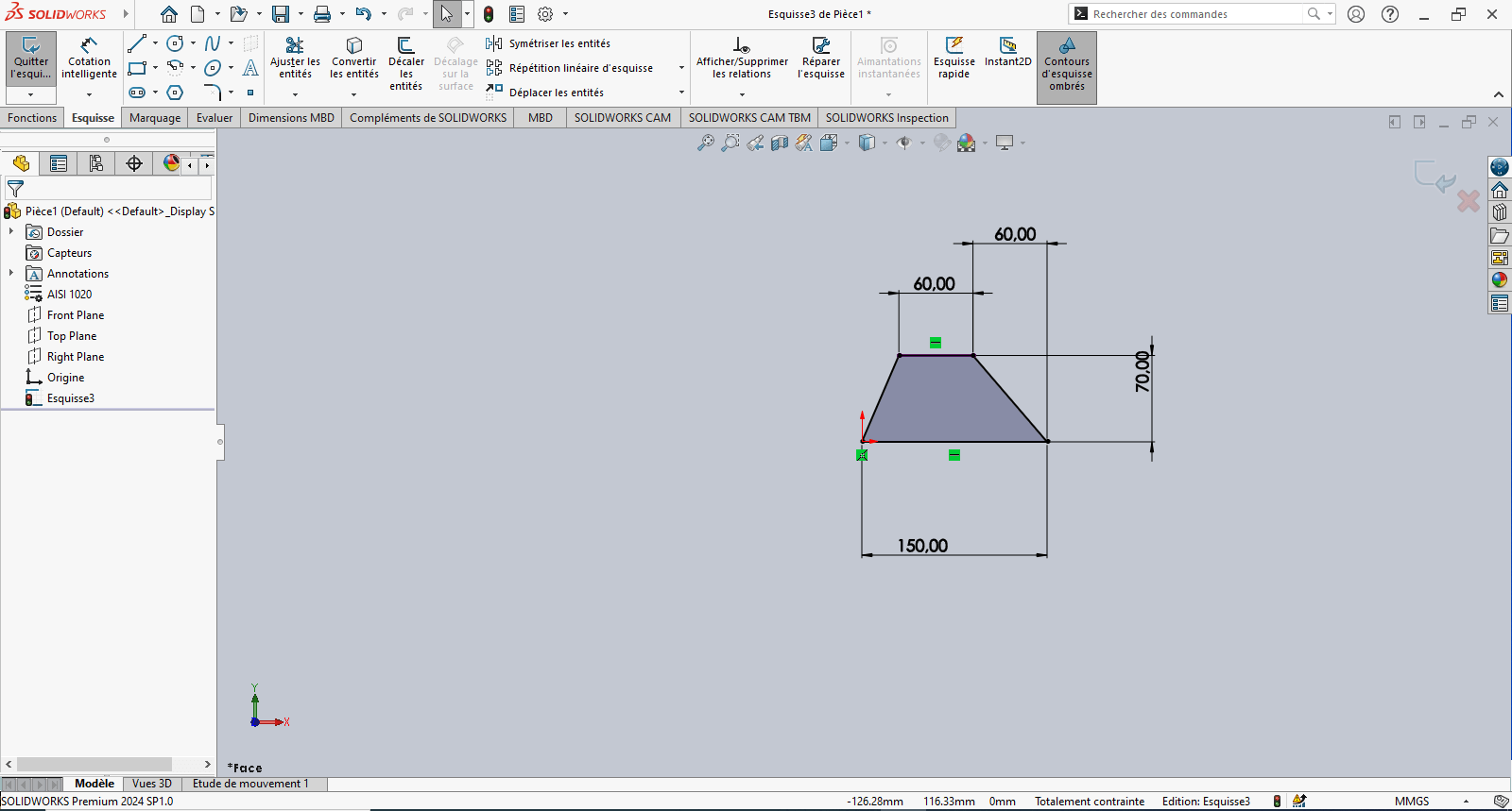
Tip: Reference the origin to fix the sketch and improve stability
- Use the Offset Entities tool to offset the trapezoid 10 mm inward
-
If the offset direction is incorrect, reverse it in the Property Manager
-
Use the Line tool again to draw a vertical line starting from the base of the 150 mm horizontal segment
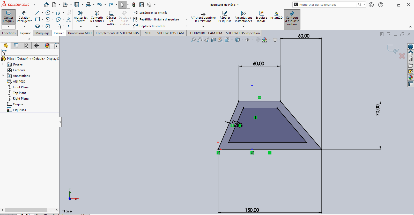
- Apply Smart Dimensioning to position this line relative to a fixed reference point
- Verify that the sketch is fully constrained
- If not, apply necessary constraints to stabilize the geometry
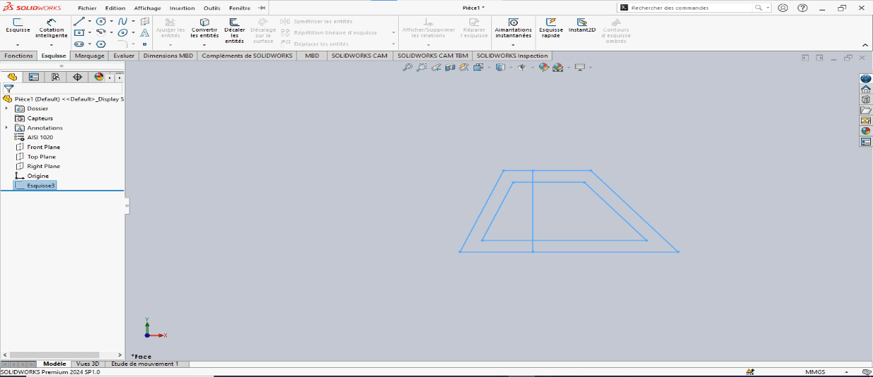
- Exit the sketch
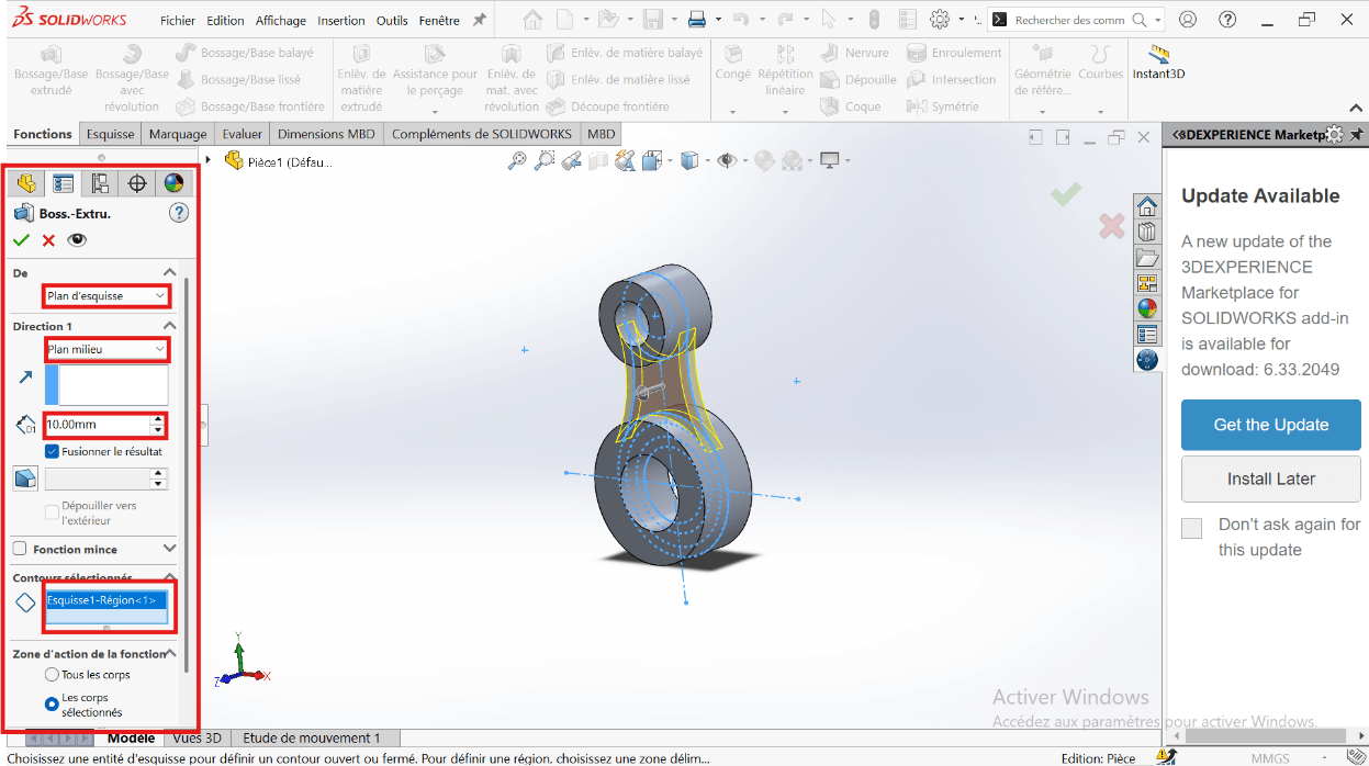
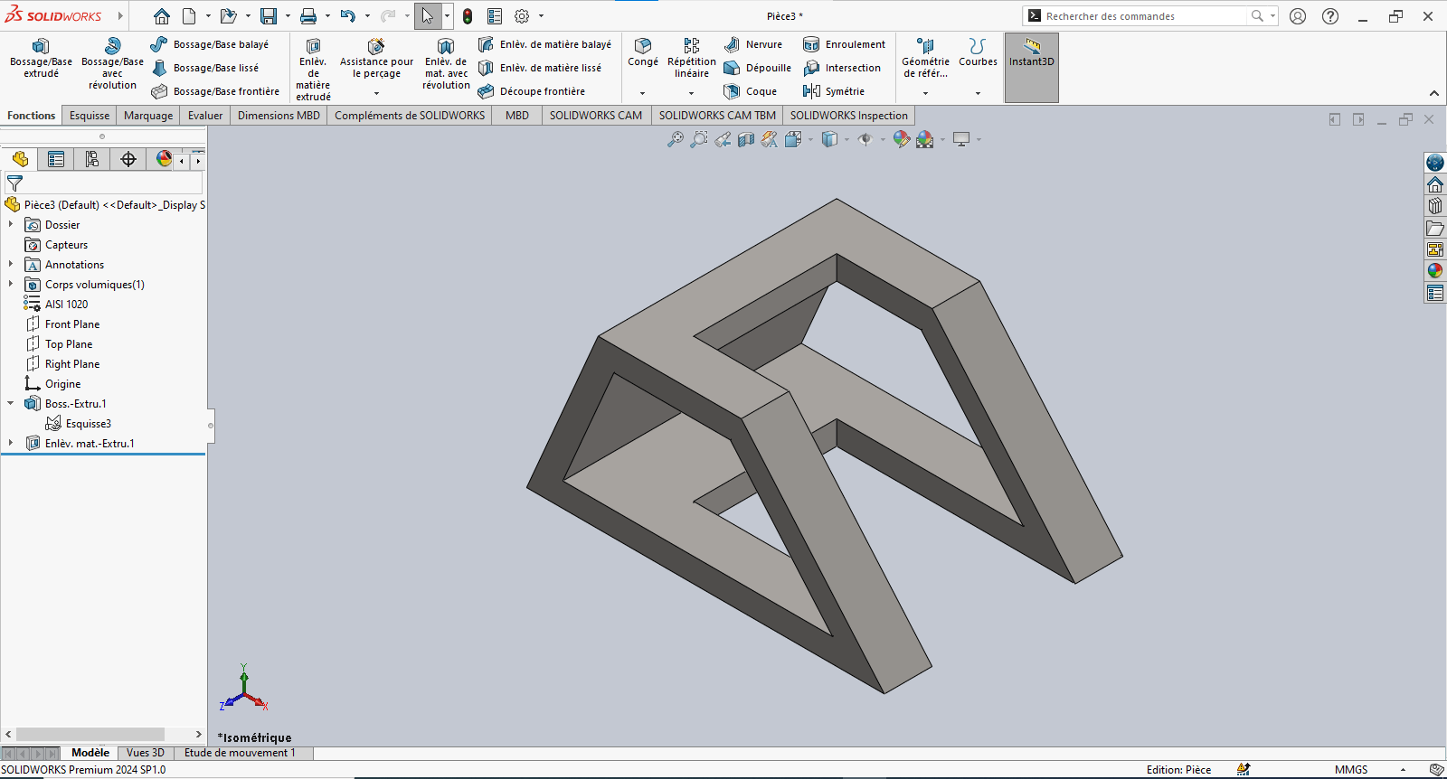
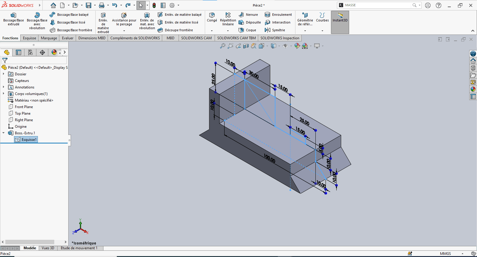
—> 3. Creating the 3D Volume
---> Boss-Extrude (Solid)
-
Navigate to Features > Extruded Boss/Base
-
Select the sketch entities to extrude
-
Set extrusion properties:
- Direction: Select Mid Plane
- Depth: 100 mm
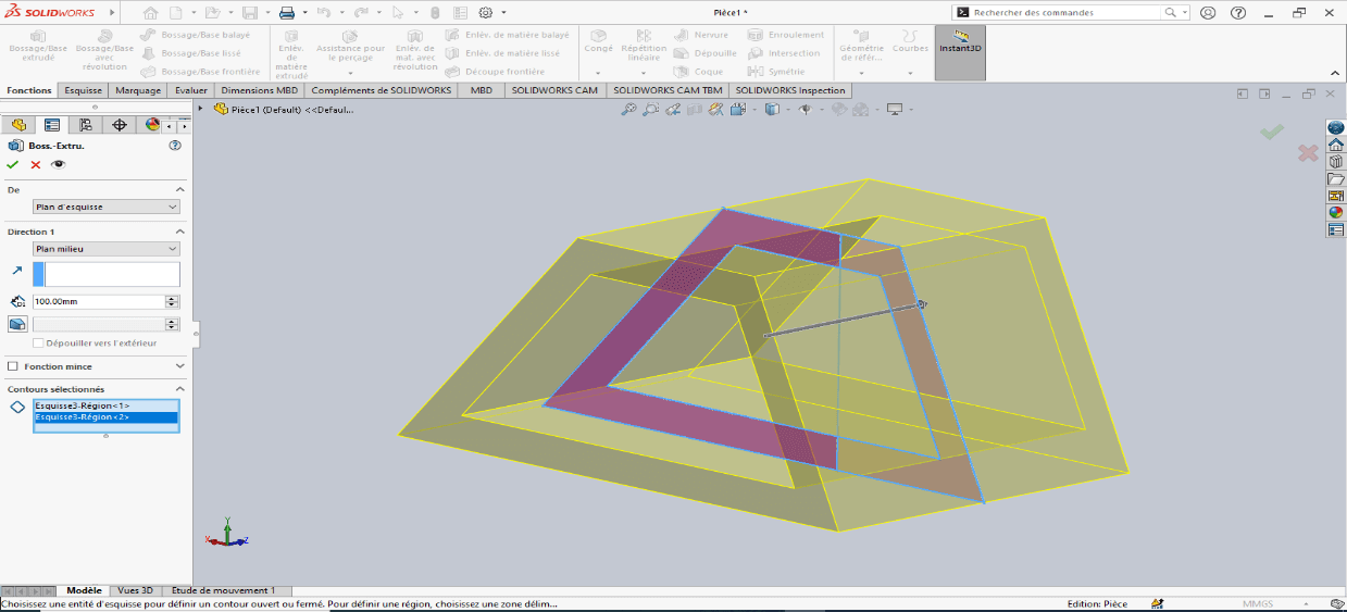
-
Confirm by clicking OK
---> Cut-Extrude (Material Removal)
-
Select Extruded Cut
-
Choose the entities to remove
-
Set extrusion properties:
- Direction: Select Mid Plane
- Depth: 60 mm
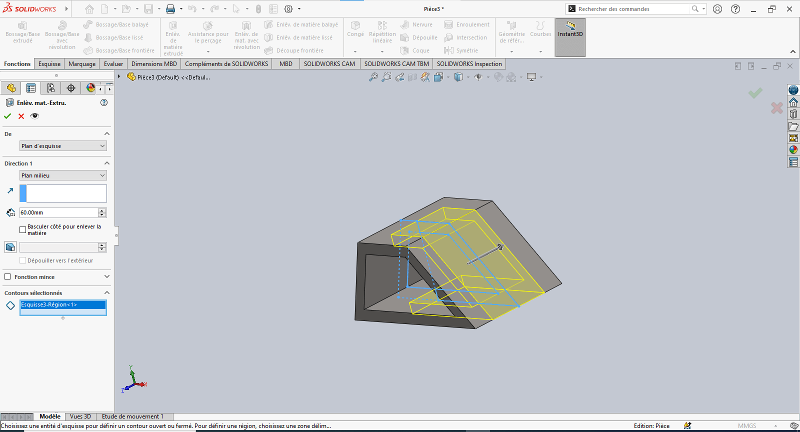
-
Confirm by clicking OK
—> 4. Evaluating Part Mass
- Type “Mass” in the search bar
- Click on Mass Properties
- Review the calculated mass based on geometry and material assignment
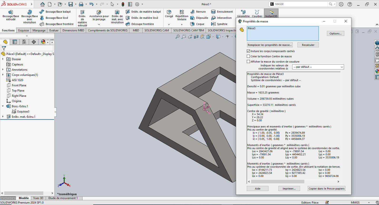
The piece mass is : 1633.25 gramms
Modeling of the Fourth Piece
Section titled “Modeling of the Fourth Piece”Unit System
Section titled “Unit System”- MMGS (Millimeter, Gram, Second)
- Decimals: 2
- Hole Specification: All holes are through unless otherwise specified
- Material: Aluminum Alloy 1060
- Density: 0.0027 g/mm³
—> 1. Updating Material Settings
- Right-click on Material: “Not Specified”
- Select Edit Material
- In the Material tab:
- Navigate to SolidWorks Materials > Aluminum Alloys > 1060 Alloy
- Click Apply, then Close
—> 2. Preparing the Workspace
- Select the Front Plane and click Sketch
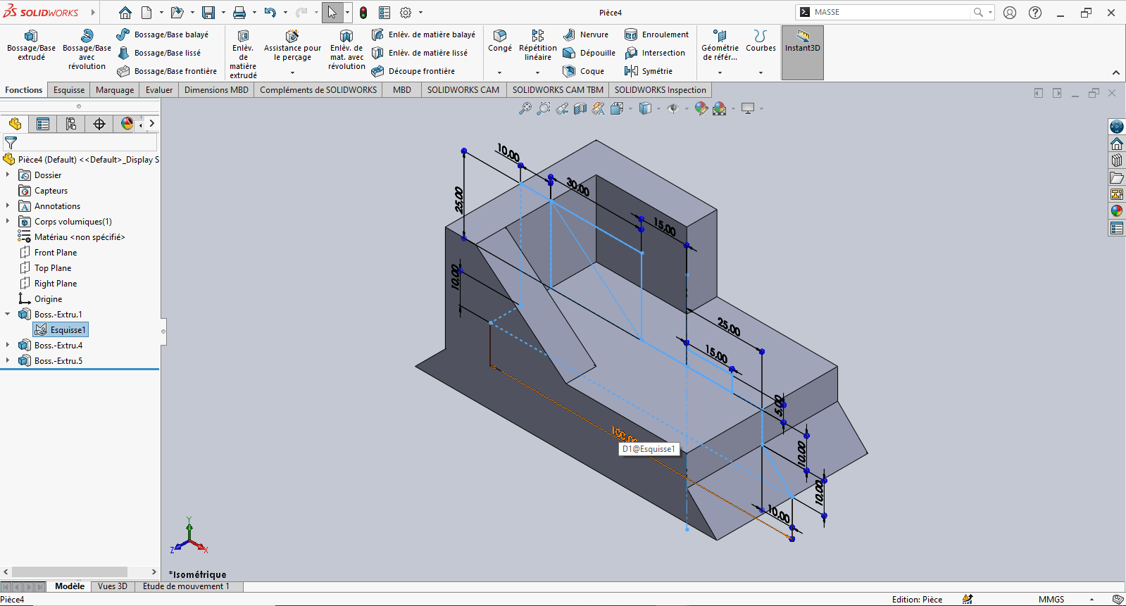
—> 3. Creating the Sketch
- Use the Line tool to draw a profile similar to the front view of the part
- Use Smart Dimension to assign dimensions to the sketch elements
- Reference the origin wherever possible for stability
- Exit the sketch
—> 4. Creating the Volume – Extrusions
---> First Extrusion
- Click Features > Extruded Boss/Base
- In the Feature Manager:
- Set extrusion direction to Mid Plane
- Set Depth to 50 mm
- Select the appropriate contour and confirm
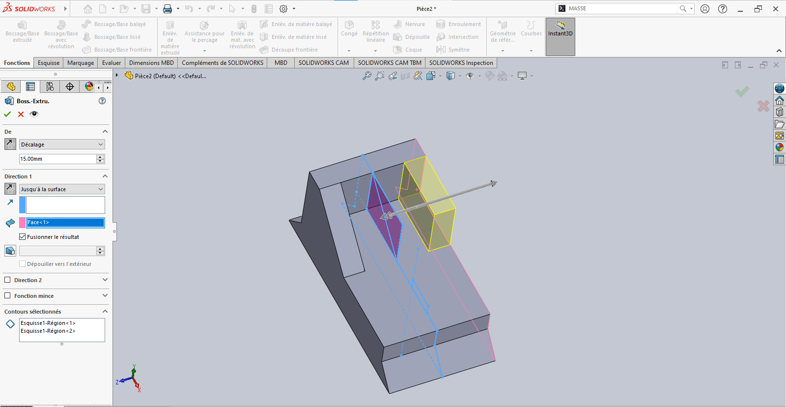
---> Second Extrusion
-
Return to the same sketch
-
Click Extruded Boss/Base
- Set an offset of 15 mm
- Define the direction carefully (flip if needed)
- Choose Up to Surface as the end condition if required, and select the target face

-
Validate the extrusion

---> Third Extrusion
-
Repeat the previous step
- Again, pay attention to offset direction
- Use Up to Surface for precise alignment
-
Confirm the operation
—> 5. Revolved Feature
-
In the sketch, select Revolved Boss/Base
- Specify the revolution angle
- Select the profile to revolve
- Choose the axis of revolution
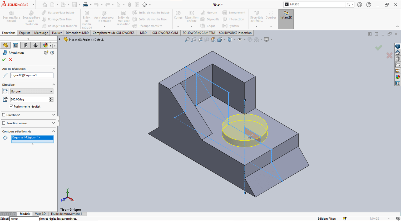
-
Confirm the feature
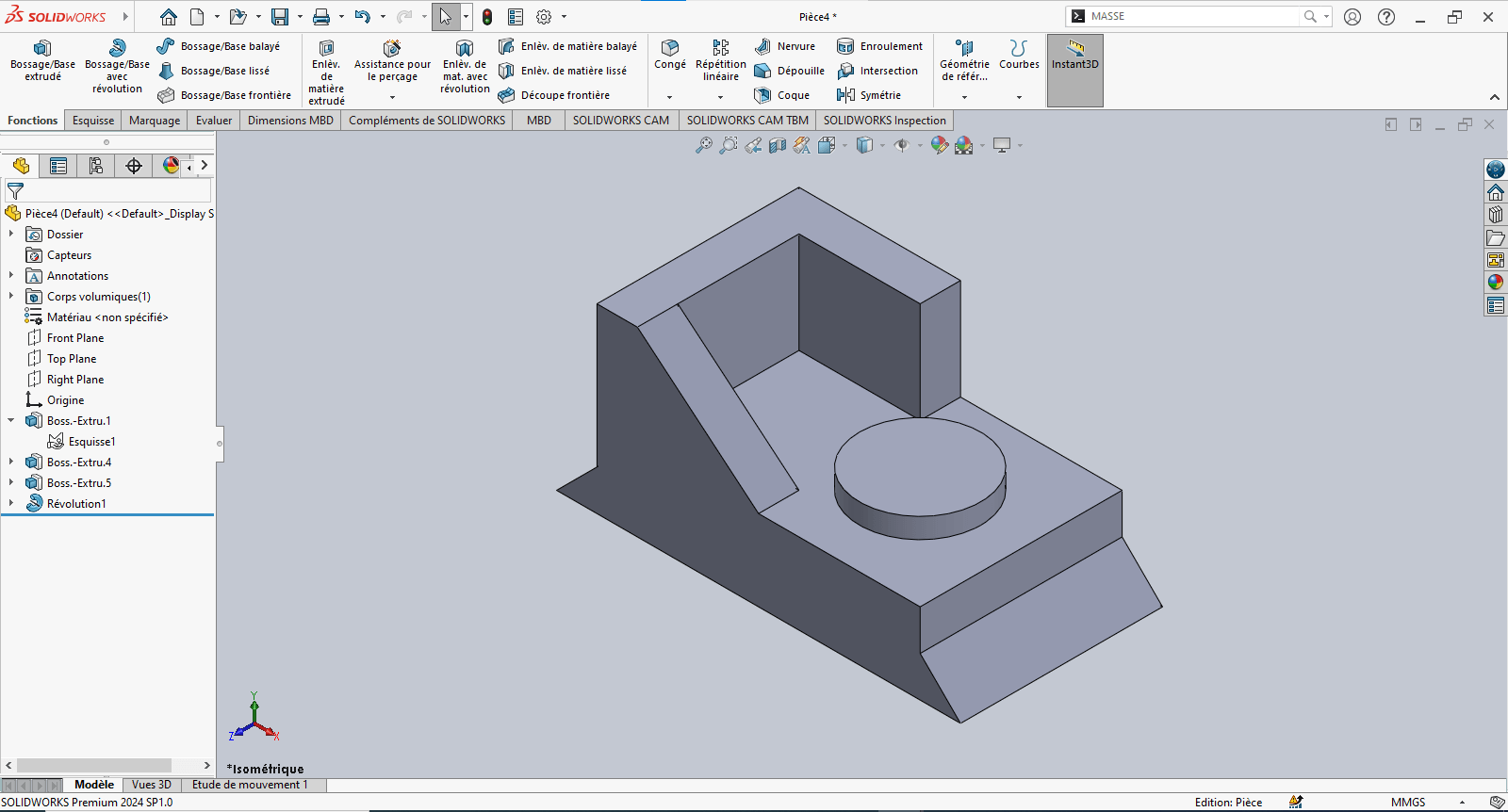
—> 6. Adding Fillets
- Use the Fillet tool to apply a 2 mm radius to the designated edge(s)
- Validate the fillet
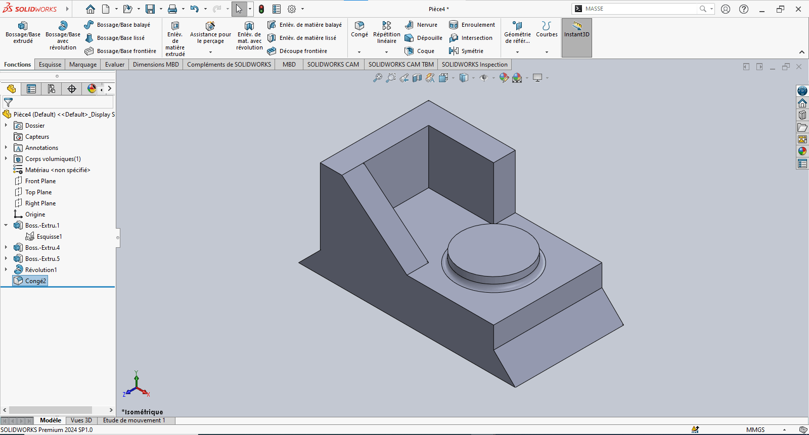
—> 7. Evaluating the Part’s Mass
- Type “Mass” in the search bar
- Click on Mass Properties
- Review the calculated mass value
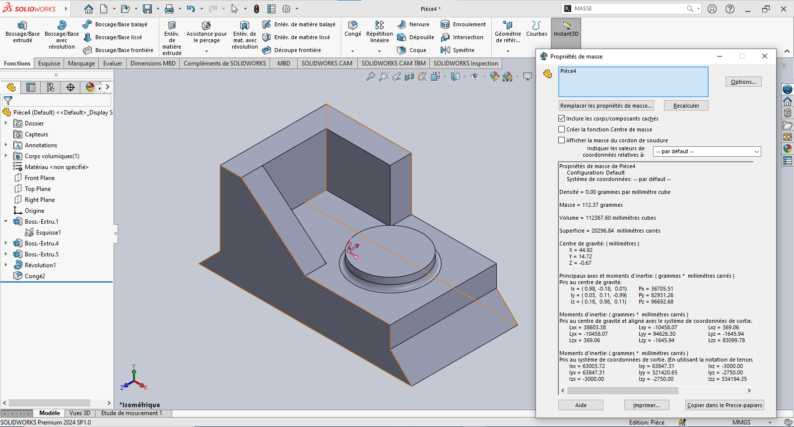
The piece mass is : 112.37 gramms
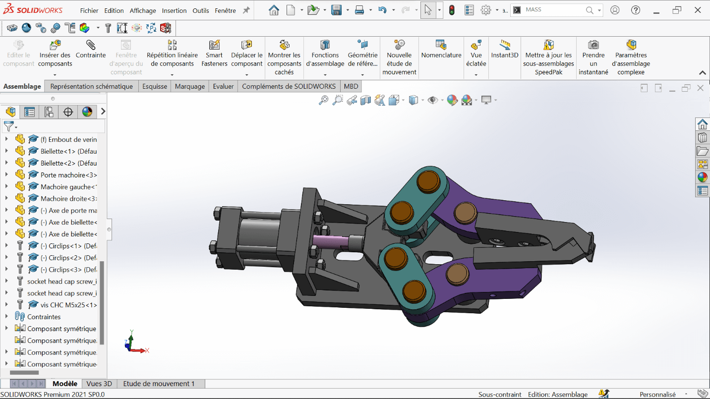
Assembly – Mechanical Gripper
Section titled “Assembly – Mechanical Gripper”Objective
Section titled “Objective”This stage of the test involves assembling various components to form a mechanical gripper. After downloading the provided .zip file, the goal is to assemble the given parts using appropriate constraints.
Constraints and Functions Used in the Gripper Assembly
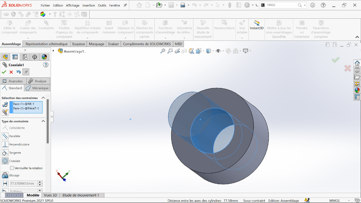
Section titled “Constraints and Functions Used in the Gripper Assembly”—> 1. Coaxial Constraint
This constraint aligns two cylindrical or circular axes (holes, shafts, cylinders) to share the same center axis.
Example: Aligning a shaft with its corresponding hole ensures proper axial alignment.
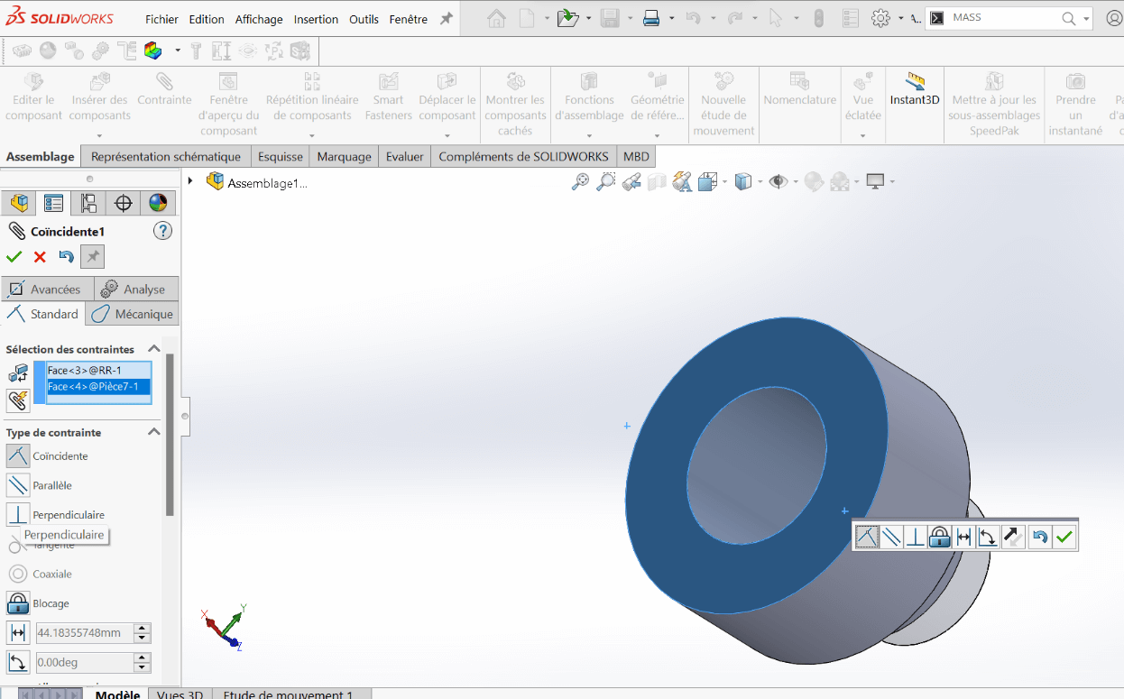
—> 2. Coincident Constraint
This constraint forces two planar or linear surfaces to touch, making them coplanar or flush.
Usage: Used to attach one part directly against another.
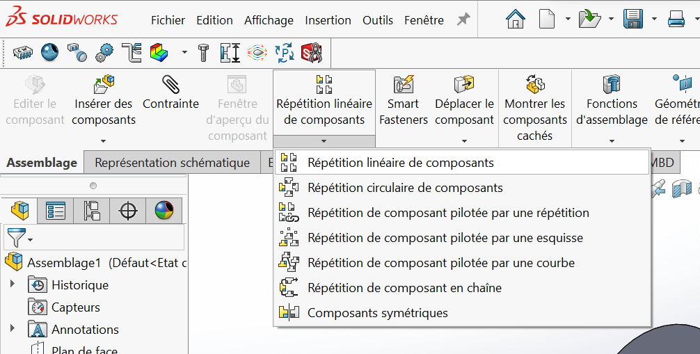
—> 3. Symmetric Components Function Under the Linear Component Pattern feature, this function generates a mirrored component from a parent part across a defined reference plane.
Assembly Steps
Section titled “Assembly Steps”- Open SolidWorks, then open the file
ASSEMBLAGE PINCE.
- Insert the following parts to complete the mechanical gripper:
- Connecting Links (Biellettes)
- Jaw Holders (Porte Mâchoire)
- Left and Right Jaws (Mâchoire Gauche & Droite)
- Link Axles (Axe de Biellette)
- Jaw Holder Axles (Axe Porte Mâchoire)
- M5×16 Screws
- M5×25 Screws
- Circlips
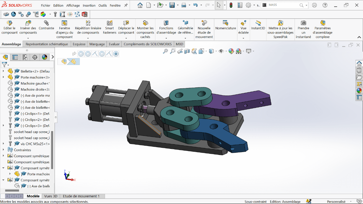
Positioning the First Link
Section titled “Positioning the First Link”- Insert the first biellette (link)
- Apply Coaxial and Coincident constraints to mount it on top of the cylinder rod end
Adding the Second Link
Section titled “Adding the Second Link”- Insert the second biellette underneath the first one, with the rod end in between
- Use Coaxial and Coincident constraints for alignment
- Add a Coincident constraint between the two link faces for perfect overlap
Creating Symmetry
Section titled “Creating Symmetry”- Use the Top Plane and the Symmetric Components tool to mirror and complete all four links required for the gripper
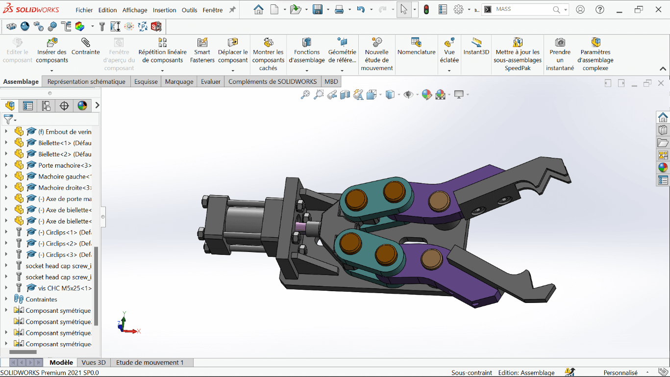
Adding the Jaw Holders
Section titled “Adding the Jaw Holders”- Insert the Jaw Holder using Coaxial and Coincident constraints
- Apply symmetry with respect to the Top Plane, as done previously
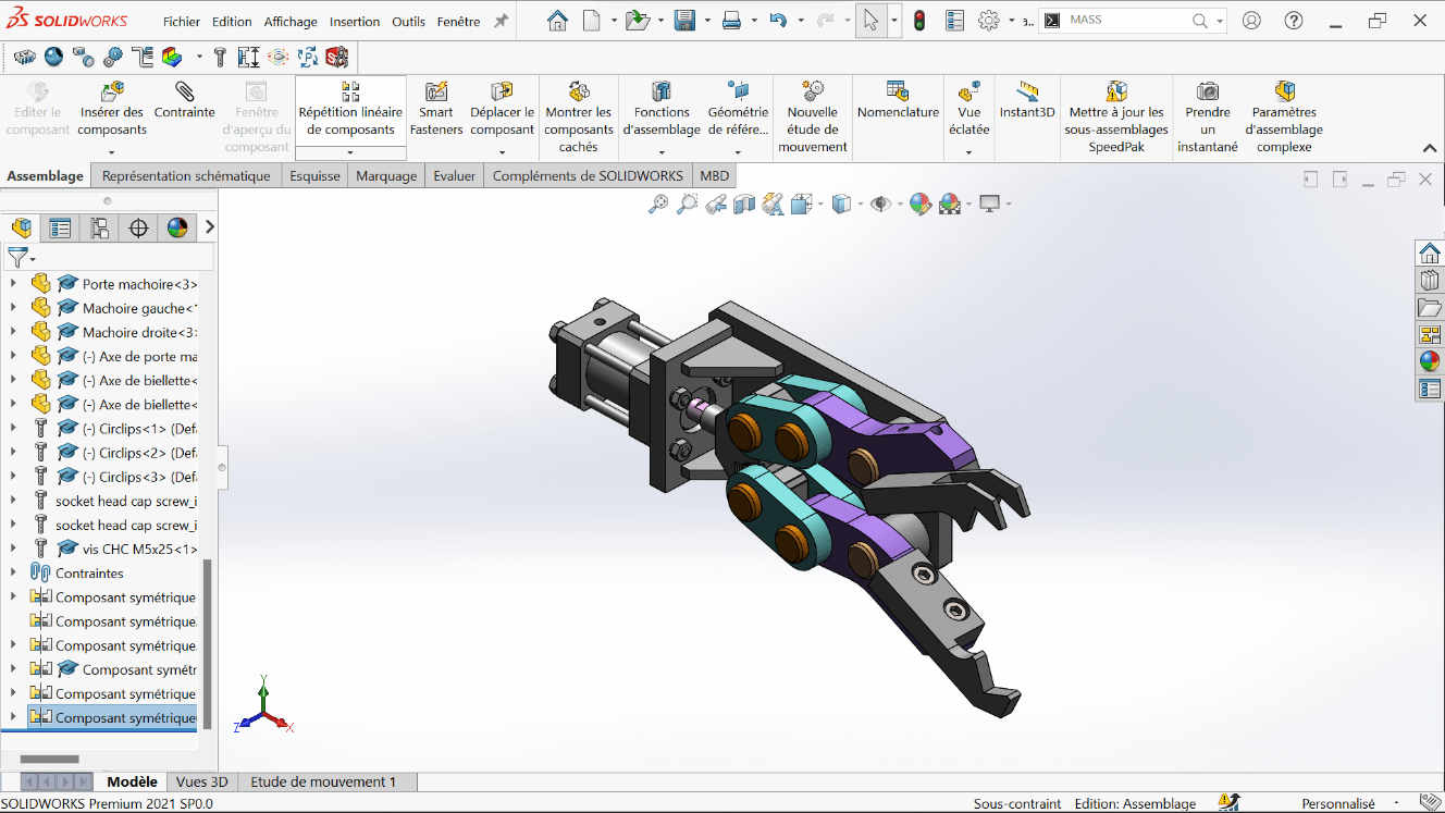
Finalizing Assembly
Section titled “Finalizing Assembly”- Insert the jaws (left and right)
- Add all fasteners and fixings:
- M5×16 screws
- M5×25 screws
- Link and jaw axles
- Circlips for locking
- This results in the complete mechanical gripper
Complementary Tasks
Section titled “Complementary Tasks”—> 1. Center of Gravity – Open Position
- Fix the rod end at the minimum extension
- Analyze the center of gravity of the entire assembly in this fully open position
| Configuration | X (mm) | Y (mm) | Z (mm) |
|---|---|---|---|
| Fully Open | -29.15 | 0.16 | 19.86 |
—> 2. Center of Gravity – Closed Position
- Fix the rod end at the maximum extension
- Analyze the center of gravity in this fully closed configuration
| Configuration | X (mm) | Y (mm) | Z (mm) |
|---|---|---|---|
| Fully Closed | -25.78 | 0.06 | 19.86 |
Errors Encountered
Section titled “Errors Encountered”Problem
Section titled “Problem”During the installation of SolidWorks, I encountered an issue that initially prevented successful setup.
Solution
Section titled “Solution”The problem was resolved after watching a step-by-step tutorial video that clearly demonstrated the correct installation procedure and highlighted settings we had previously overlooked.
Perspectives
Section titled “Perspectives”-
Part Optimization: Future versions of the mechanical components could explore new materials or lightweight geometries to reduce mass and improve energy efficiency.
-
Smarter Gripping Mechanisms: Integration of force sensors, soft grippers, or motor feedback could make the gripper more adaptive to different object shapes and textures.
-
System Integration: The validated modules can be scaled into more complex robotic systems, such as mobile manipulators or industrial automation platforms.
-
Simulation Before Prototyping: Leveraging SolidWorks Motion Studies, MATLAB/Simulink, or ROS-based environments for dynamic testing and control strategy validation before fabrication.
Resources
Section titled “Resources”Installation Guides
Section titled “Installation Guides”-
Official SolidWorks Installation Guide (EN)
Detailed instructions to install SolidWorks on a single computer. -
SolidWorks Admin & Deployment Guides
For advanced installations, network licenses, and administrative deployments. -
SolidWorks Downloads Portal
Access to installation files, service packs, and updates (login required).
Official Tutorials & Manuals
Section titled “Official Tutorials & Manuals”-
Student’s Guide to Learning SolidWorks (PDF)
A comprehensive beginner workbook with hands-on exercises. -
MySolidWorks – Online Training Hub
Interactive tutorials, certification prep, and beginner-to-advanced courses.
Beginner-Friendly Video Tutorials
Section titled “Beginner-Friendly Video Tutorials”-
SolidWorks Tutorial for Beginners #1 – CAD CAM Tutorials (YouTube)
Start modeling with sketches, constraints, and extrusion. -
SolidWorks 2020 Full Beginner Tutorial – Aryan Fallahi (YouTube)
A concise intro to interface, part design, and assemblies. -
SolidWorks Tutorials for Beginners (Website)
Detailed walkthroughs on tools, menus, and modeling strategies.
Additional Resources
Section titled “Additional Resources”-
Last Minute Engineers – CAD & Arduino Projects
Perfect for blending SolidWorks with real-world embedded projects. -
GrabCAD Library – SolidWorks Files
Thousands of free SolidWorks models and parts to download and explore. -
SolidWorks Forums (EN)
Ask questions, get help, and join discussions with the global community.