1rst Test
Ojectives
-
Dimension a Suitable Power Supply
- Analyze voltage and current requirements for all components.
- Design and build a reliable power source to independently supply the circuit (e.g., battery with voltage regulation).
-
Implement and Utilize an Inertial Sensor (Gyroscope + Accelerometer)
- Select an I2C-capable inertial measurement unit (e.g., MPU6050).
- Understand its operating principles and process orientation and motion data.
-
Real-Time Interpretation and Display of Motion Data
- Detect directional hand movements and measure acceleration.
- Display results dynamically on an LCD and optionally through the serial monitor.
Summary
Access the kicad and arduino files by clicking here.
Materials
Proccess
Power Supply Design
System Overview
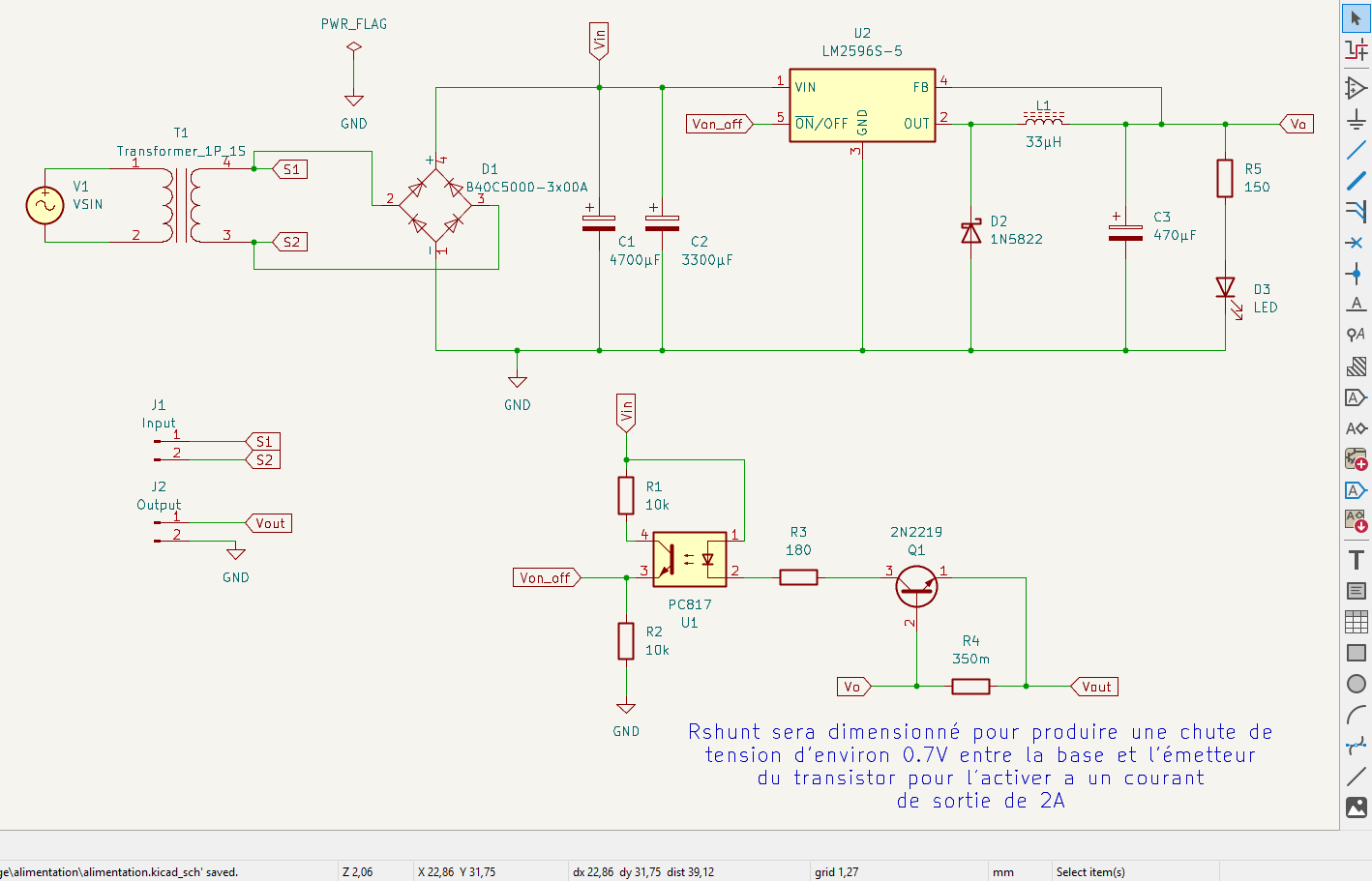
A custom-designed power supply built around a 220V to 15V transformer, bridge rectifier, filtering capacitor, and a buck regulator (LM2596-5), with added current limiting circuitry and visual indicators.
Transformer
-
Transformer: 220V/15V – 30VA
-
Current Output:
I2 = 30VA / 15V = 2A
-
Provides galvanic isolation and sufficient power for the system.
Rectifier
- Type: Full-wave bridge
- Specs: 3A average current, ≥ 21.21V reverse voltage
- Component: 3A/400V molded rectifier (recycled from a PC PSU)
Filter Capacitor
-
Target Ripple (∆Ve): 3.5V
-
Worst-case current: 2.01A
-
Calculation:
C = 2.01 / (100 x 3.5) ≈ 6483.9 µF
-
Used : 4700µF + 3300µF = 8000µF / 25V
Regulation
--> LM7805 Limitations
- Max 1.5A output → insufficient
- High heat dissipation → requires heatsink
--> LM2596-5 Buck Converter
- Max current: 3A
- Current-limited externally to 2A
- Efficient with minimal heat → no heatsink needed
- Module includes: regulator, capacitors, diode, and inductor
LED Indicator
-
LED Specs: 2.1V @ 20mA
-
Resistor value:
R = (5V - 2.1V) / (0.02A) = 145Ω
Use R = 150Ω (E24 standard)
-
Power dissipated:
P = R.I2 = 145 / (0.02)2 = 58mW
Use 1/4W resistor
Current Limiting Cell
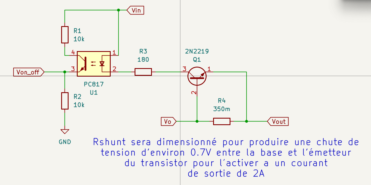
-
Components:
- Transistor: 2N2222
- Optocoupler: PC817
- Shunt Resistor: R4 = 0.35Ω
-
Operation:
- Below 2A → regulator ON
- ≥ 2A → Q1 conducts → optocoupler cuts off LM2596 via ON/OFF pin
-
R3 Calculation:
R3 = (12.5V - 1.2V - 0.2V) / 0.02A ≈ 555Ω
Use 600Ω, 1/4W
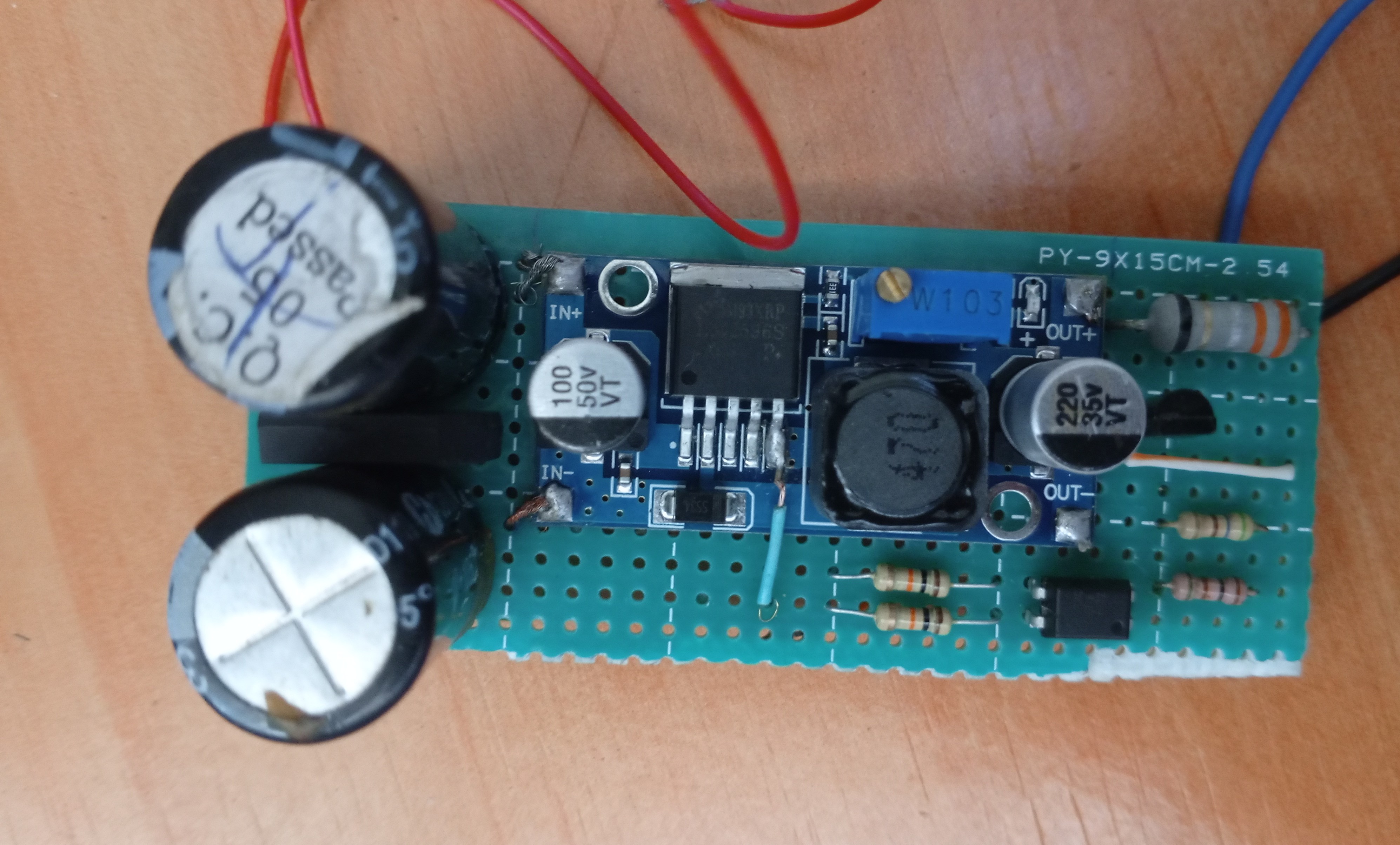
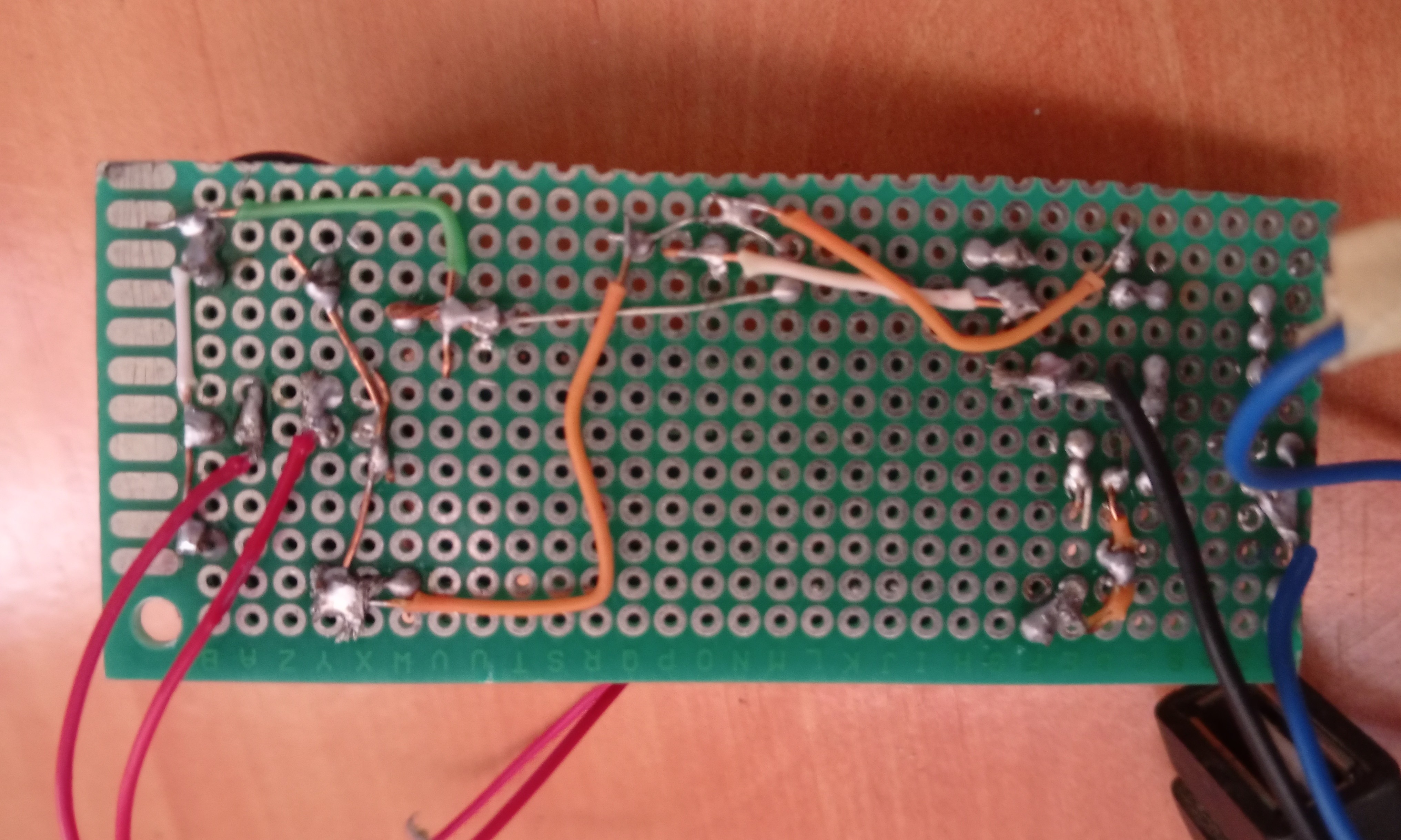
Implementation Photos
Implementation of the Navigation System
The aim of this documentation is to provide an exhaustive description of the technical approach taken to testing the gyroscope and accelerometer. It details the selection and wiring of the hardware, the design of the code, the test procedure implemented, and the in-depth analysis of the results obtained. More than a simple report, this document is intended to serve as a technical reference for members of the electronics, mechanics and IT team, facilitating understanding and multidisciplinary collaboration. This document is also intended to serve as a technical reference for anyone wishing to work on a similar project, so as not to reinvent the wheel, as the saying goes, but to build on what already exists and add the desired new features.
Description of Materials Used
Microcontroller & Development Board
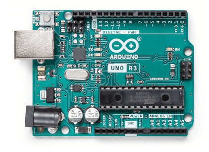
The heart of our gyroscope and accelerometer test system is based on the Arduino Uno R3 board, a microcontroller development platform widely adopted for its ease of use and versatility.
This board integrates the Atmel ATmega328P microcontroller, a key component for I/O management and sensor data processing.
---> Microcontroller
- Model: Atmel ATmega328P
- Architecture: 8-bit AVR
- Clock Frequency: 16 MHz (quartz oscillator), providing sufficient processing capacity for inertial sensor data acquisition and processing tasks.
---> Memory
- Flash Memory: 32 KB (including 0.5 KB used by the bootloader), for storing the control program.
- SRAM (Static RAM): 2 KB, for temporary storage of variables and processed data (such as sensor readings).
- EEPROM: 1 KB, for persistent storage of data (configurations, calibrations) that need to be retained even after a power failure.
---> Power Specifications
- Operating Voltage: 5V
- Supply Voltage (Recommended): 7-12V (via jack or VIN pin), allowing flexible powering of the board from various sources (battery, AC adapter).
---> I/O Pins
- Digital I/O: 14 digital pins (6 of which can be used as PWM outputs).
- Essential for communication with various peripherals and actuators.
- Mainly used for serial communication and I2C interfacing in this test.
- Analog I/O: 6 analog input pins.
- Useful for reading analog sensors.
- Less critical for the MPU6050, which communicates digitally.
---> Communication Interfaces
- I2C (TWI): Present on pins A4 (SDA) and A5 (SCL), essential for communication with the gyro/accelerometer module (MPU6050).
- SPI: Supported on pins 10 (SS), 11 (MOSI), 12 (MISO), 13 (SCK).
- UART (Serial): Via pins 0 (RX) and 1 (TX), used for communication with the computer via the serial monitor (for debugging and data display).
- USB Connectivity: USB-B port for programming and serial communication with a computer.
---> Bootloader
- Pre-installed, allowing easy program uploads via the USB port without requiring an external programmer.
---> Why Arduino Uno ?
The Arduino Uno was chosen for its robustness, abundant documentation, and active community, making prototyping and rapid debugging of sensor interactions much easier.
Its 5V operating voltage and the availability of the I2C interface via dedicated pins (A4, A5) make it an ideal platform for this initial test.
LCD Screen
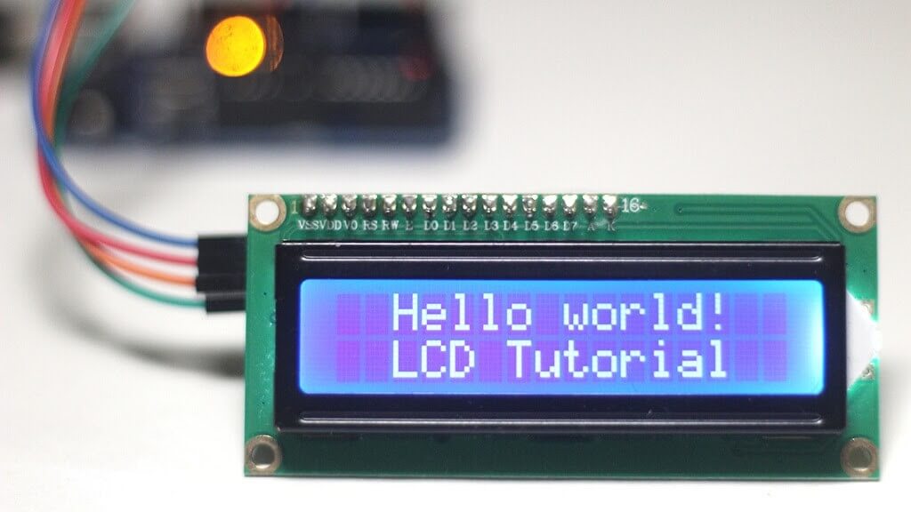
To provide instant and clear visual feedback on the movements detected by the MPU6050, we have integrated a 16x2 LCD display (16 characters on 2 lines) with an I2C interface module. This type of display combines a standard LCD display with an extension module based on the PCF8574 integrated circuit, greatly facilitating its interfacing with the microcontroller.
---> Key Features and Benefits of the I2C LCD Display
-
Simplified I2C Interface
- The main advantage of this module is its ability to communicate via the I2C protocol.
- This significantly reduces the number of pins required on the Arduino Uno to control the display (from 7–11 pins in parallel mode to just two: SDA and SCL).
- Frees up valuable pins for other sensors or actuators.
-
Character and Message Display
- The display can show alphanumeric text, numbers, and special characters.
- Ideal for displaying status messages, motion directions ('FORWARD', 'UP', etc.), or sensor values.
-
Custom Characters
- The LiquidCrystal_I2C.h library enables the creation and display of custom characters, such as arrow icons.
- This enhances the intuitiveness and visual appeal of movement direction displays.
-
Backlight Control
- The I2C module features an integrated LED backlight, which can be activated or deactivated via software.
- Improves readability in different lighting conditions.
-
Contrast Potentiometer
- A potentiometer is present on the I2C module, allowing manual adjustment of display contrast for optimal visibility.
-
I2C Address
- The display communicates via a specific I2C address (frequently 0x27 or 0x3F).
- This address is configured in the code to ensure correct communication with the Arduino.
-
Supply Voltage
- The module operates at 5V, making it directly compatible with the Arduino Uno's supply output.
---> Integration Benefits
The integration of this I2C LCD display provides an essential on-board user interface, enabling real-time motion detection results without requiring a computer connection.
It enhances the testing and demonstration experience of the system.
For a more in-depth understanding of I2C LCDs, including wiring and functionality, refer to the following detailed tutorial:
Last Minute Engineers - I2C LCD Arduino Tutorial
MPU6050
As kids, the gyroscopes at the science fair never failed to amaze us because they moved in strange ways and even seemed to defy gravity. Their unique properties make them crucial in everything from small RC helicopters to the advanced navigation system on the space shuttle.
In recent years, ingenious engineers have successfully developed micromachined gyroscopes. These MEMS (microelectromechanical system) gyroscopes have paved the way for an entirely new set of innovative applications, including gesture recognition, enhanced gaming, augmented reality, panoramic photo capture, vehicle navigation, and fitness monitoring, to name a few.
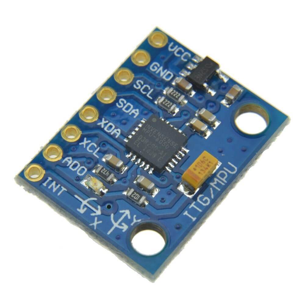
Without a doubt, the gyroscope and accelerometer are each exceptional in their own way. However, when we put them together, we can obtain incredibly precise data about an object’s orientation. This is where the MPU6050 enters the picture. The MPU6050 includes a gyroscope and an accelerometer, allowing us to measure rotation along all three axes, static acceleration due to gravity, and dynamic acceleration due to motion.
Le module au cœur de ce test est le MPU6050, un composant clé pour la perception de mouvement dans de nombreux projets robotiques et d'inertie. Il s'agit d'une unité de mesure inertielle (IMU - Inertial Measurement Unit) 6 axes, combinant un accéléromètre et un gyroscope sur une seule puce.
---> MPU6050 Key Features and Functions
-----> 6-Axis Sensor in a Single Component
The MPU6050 integrates two essential sensors for motion detection:
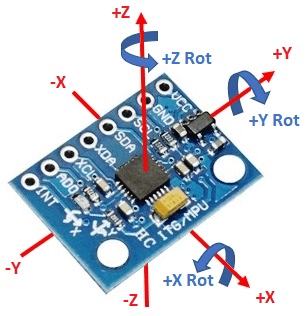
------> **3-Axis Accelerometer
- Measures linear acceleration along the X, Y, and Z axes.
- Can detect gravity, helping determine the sensor's static orientation.
- Configurable measurement ranges: ±2g, ±4g, ±8g, ±16g.
------> 3-Axis Gyroscope
- Measures angular velocity (rotation) around the X (Roll), Y (Pitch), and Z (Yaw) axes.
- Configurable measurement ranges: ±250°/s, ±500°/s, ±1000°/s, ±2000°/s.
---> On-Board Digital Motion Processor (DMP)
The MPU6050 is distinguished by its DMP, an on-board hardware processing engine.
This processor is capable of merging gyroscope and accelerometer data directly on the chip, generating precise quaternions and Euler angles (Yaw, Pitch, Roll).
------> **Benefits of the DMP
- Reduces processing load on the external microcontroller (Arduino Uno), as complex sensor fusion calculations are performed by the MPU6050 itself.
- Provides more stable and reliable orientation data, minimizing gyroscope drift and accelerometer noise.
---> I2C Communication Interface
- The MPU6050 communicates with the microcontroller via the I2C protocol.
- Simplifies wiring and data management with just two data wires (SDA and SCL) in addition to the power supply.
---> **Integrated Temperature Sensor **
- The module includes a temperature sensor, useful for compensating drifts due to thermal variations.
---> Operating Voltage
- The MPU6050 operates over a voltage range of 3.3V to 5V, making it compatible with the Arduino Uno.
- No need for a voltage level converter if the module already incorporates a regulator.
---> Why MPU6050 ?
The MPU6050 was chosen for this test due to its ability to provide high-quality orientation and motion data, essential for navigation and stabilization applications.
Its efficient DMP optimizes the resources of our microcontroller, making it an ideal choice.
For more detailed technical information on the MPU6050, its internal structure, and registers, refer to the full documentation available at:
Last Minute Engineers - MPU6050 Accelerometer & Gyroscope Arduino Tutorial
Circuit Diagramm
Electric Schematic
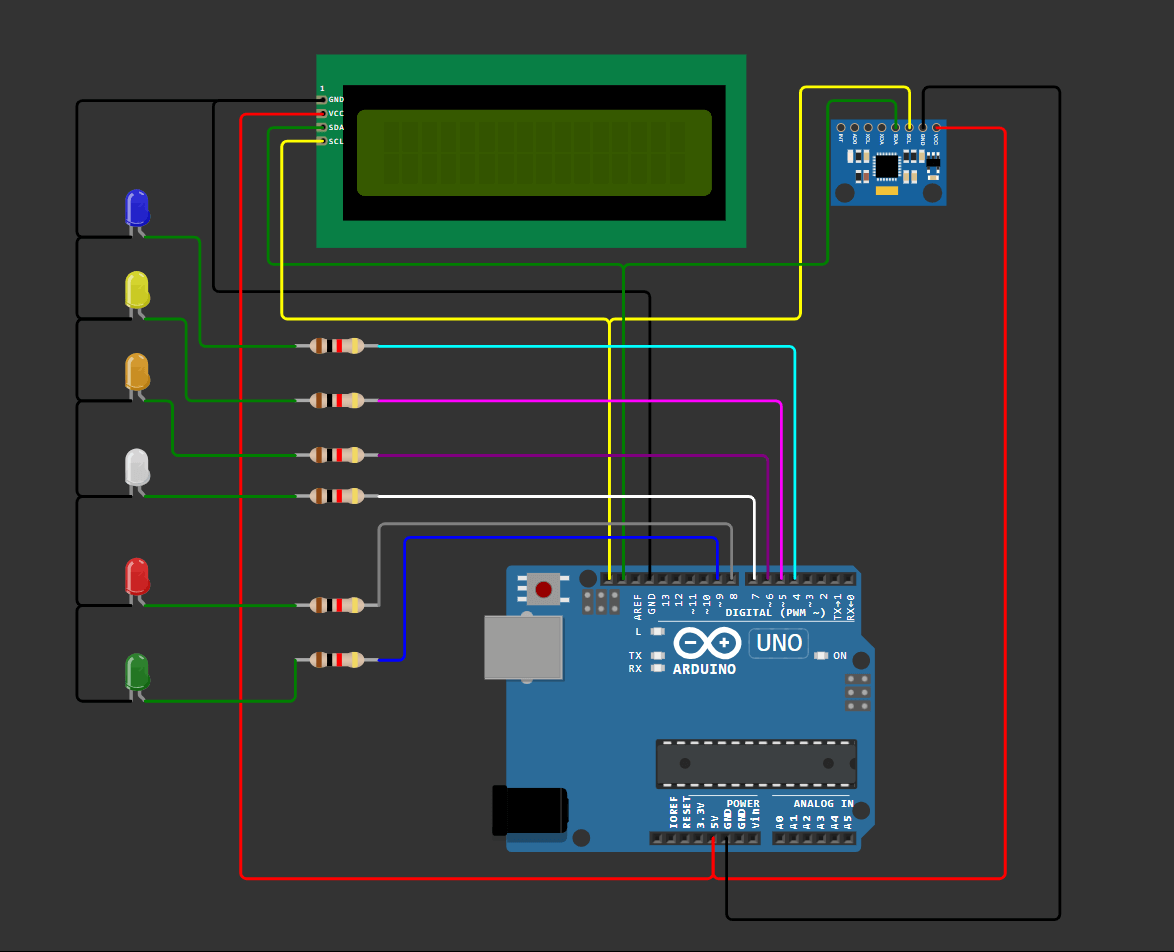
The diagram below provides a visual illustration of the component layout and electrical connections used for this test. It has been designed to provide a clear and intuitive representation of the assembly. All critical components, such as the Arduino Uno microcontroller and MPU6050 sensor, as well as the LCD (Liquid Crystal Display), are shown with their pins clearly identified (VCC, GND, SDA, SCL, etc.). We've taken care to respect the standard color conventions for wires (red for power, black for ground, and distinct colors for data signals) to improve readability and facilitate wiring verification.
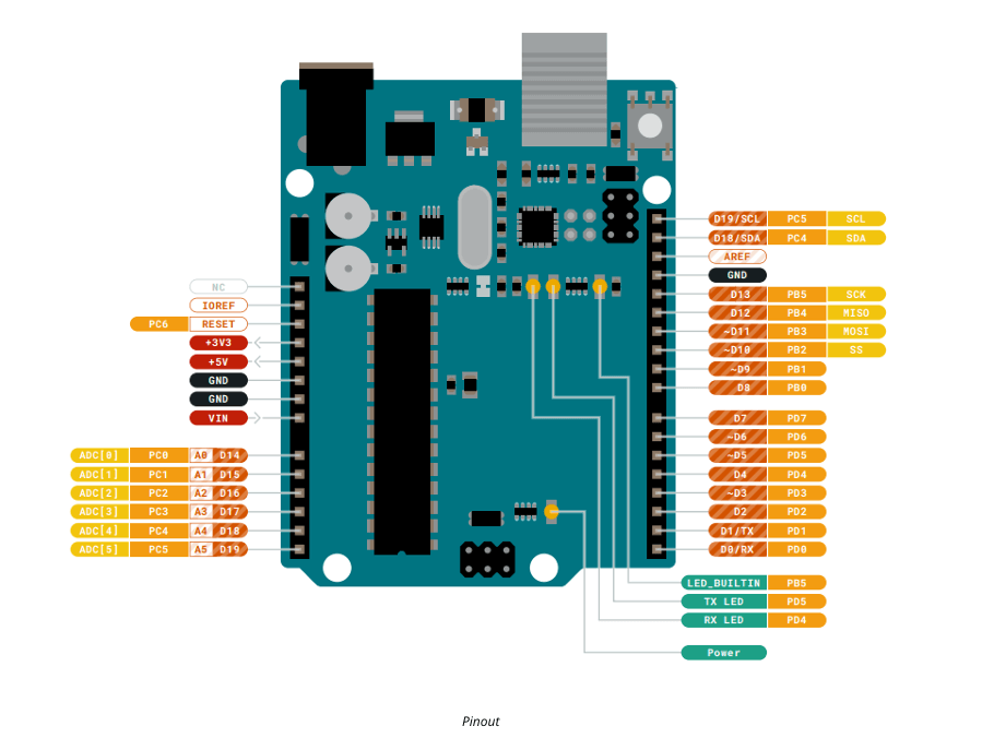
Based on this image, which shows the pinout of the UNO board, there are 20 digital pins, so if we divide the maximum current that the ATMEGA 328P can deliver by these 20 pins, we have an average current of 20mA per pin.
Resistor sizing method for efficient LED ignition.
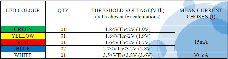
---> Resistor Calculation
Using the formula:
R = (Vout - Vth) / I
where Vout = 5V , we calculate:
RGREEN = (5V - 1.9V) / 0.015A
RGREEN = 206.6 Ohms
Using the E24 standard series, the closest standard resistor value for R_GREEN is:
RGREEN= 220 Ohms
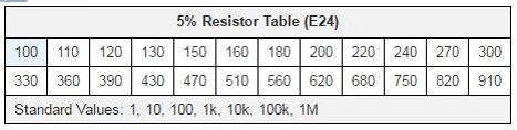
The same applies to the calculation of all remaining resistor values. The following table summarizes the normalized resistor values for each LED.

Connexion Chart
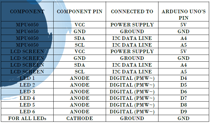
To complete the visual schematic and ensure maximum clarity, the table below exhaustively lists every wire connection between the pins of the MPU6050 sensor, the LCD display and those of the Arduino Uno microcontroller. This table is an invaluable aid for debugging and quickly checking the assembly, listing the pins of each component and their exact correspondence on the development board.
Code Developemnt
This section is dedicated to presenting and explaining the code developed to acquire and process data for the gyroscope and accelerometer module.
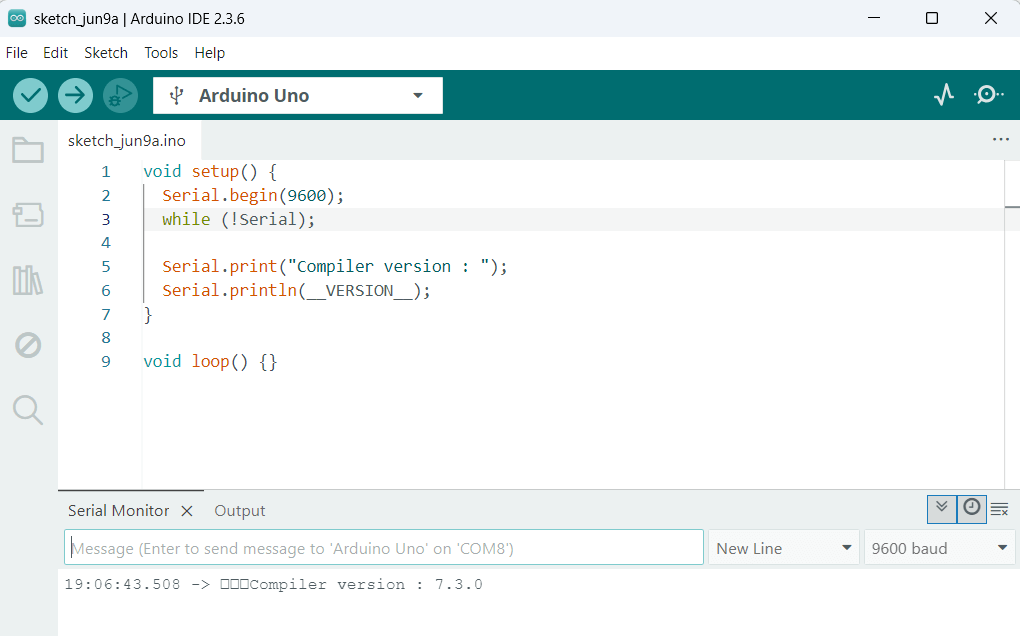
IDE version: 2.3.6
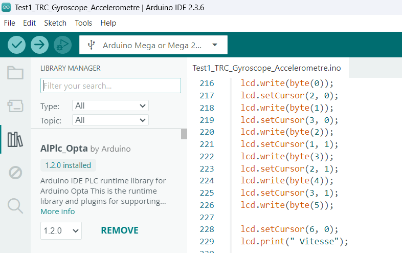
The Arduino IDE uses the integrated AVR-GCC compiler to translate C++ code (Arduino syntax) into machine language that can be understood by the ATmega328P microcontroller. This choice of environment was motivated by its simplicity, its perfect integration with the Arduino Uno board, and the wealth of libraries available, enabling rapid and efficient prototyping.
Compiler Version : 7.3.0
Libraries Used
To efficiently interact with the gyroscope-accelerometer module and the LCD screen, we have used specific libraries.
These libraries simplify access to the sensor's complex functionalities by providing ready-to-use functions and objects.
Wire.h (Arduino IDE Built-in Library)
-
Role:
- Essential for communication via the I2C (Inter-Integrated Circuit) protocol.
- The MPU6050 module and the I2C LCD display communicate with the Arduino Uno via this interface.
- Wire.h allows initialization of the I2C bus, definition of peripheral addresses, sending commands, and reading data from registers.
-
Necessity:
- The MPU6050 and LCD display are I2C peripherals, requiring this library to establish serial communication between the Arduino and these components.
I2Cdev.h & MPU6050_6Axis_MotionApps20.h (Jeff Rowberg’s Library)
-
Role:
-
These libraries are designed to exploit the MPU6050's advanced features, particularly its DMP (Digital Motion Processor).
-
I2Cdev.h:
- An abstraction layer for general I2C communications.
-
MPU6050_6Axis_MotionApps20.h:
- A high-level library that provides access to sensor fusion calculations (gyroscope and accelerometer) directly from the MPU6050's DMP.
- Includes quaternion calculations, representing orientation in 3D in a stable and precise way.
- Allows derivation of Euler angles (Yaw, Pitch, Roll).
-
-
Necessity:
- Using the DMP significantly reduces the computational load on the Arduino.
- Provides more stable orientation data, minimizing gyroscope drift and accelerometer noise.
- Essential for reliable detection of robot movements.
LiquidCrystal_I2C.h (LCD Library with I2C Interface)
-
Role:
- Simplifies interaction with an LCD Character Display via an I2C interface (requiring a PCF8574 module).
- Enables display of text, numbers, and custom characters on the screen.
-
Necessity:
- Provides direct visual feedback on system status and detected movements.
- Makes testing more interactive and information more accessible in the field.
Code Description
Just after the "Libraries Used" section, we declared constant variables:
const int led1 = 4;
const int led2 = 5;
const int led3 = 6;
const int led4 = 7;
const int led5 = 8;
const int led6 = 9;
LCD Initiliazation
LiquidCrystal_I2C lcd(0x27, 16, 2);
Custom characters for LCD display
The code defines several custom character sets (called set1_char0 to set6_char5). Each 8-byte byte array represents a 5x8 pixel character pattern. Here's an example showing the 8-byte byte array representing a heart
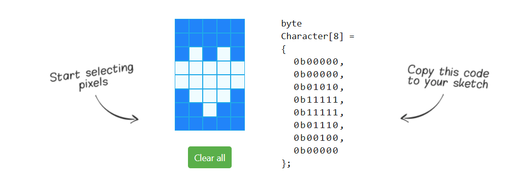
In our code, these characters are used to display symbols on the LCD screen that represent directions of movement (for example, an arrow to the left or right).

• Each array (for example, set1_char0) contains 8 bytes. Each byte represents a line of 5 pixels. A 1 means the pixel is on, 0 means it's off. For example, 0b11111 means that the first 5 pixels of the line are on.
Character set display functions
There are six functions, displaySet1() to displaySet6(), each responsible for displaying a specific set of custom characters on the LCD screen. Each of these functions takes a float value parameter.
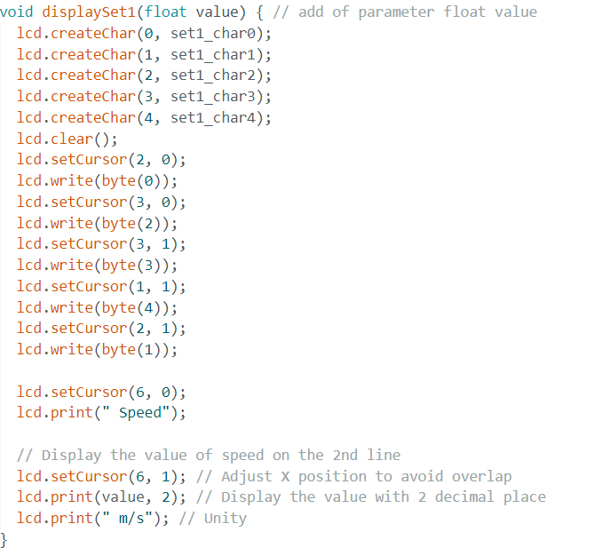
--- > Custom Character Functions
-
lcd.createChar(index, data);- Loads a custom character into the LCD memory at a specific index (0 to 7).
-
lcd.write(byte(index));- Displays the custom character stored at the given index.
---> LCD Control Functions
-
lcd.clear();- Clears all contents from the LCD screen.
-
lcd.setCursor(col, row);- Defines the cursor position on the LCD screen where the next character will be displayed.
col→ Column (0 to 15 for a 16x2 LCD).row→ Line (0 or 1).
---> Displaying Text and Values
-
lcd.print(" Speed");- Displays
"Speed"text on the first line of the LCD display.
- Displays
-
lcd.print(value, 2);- Displays value (e.g., acceleration magnitude) on the LCD screen with two decimal places.
---> Displaying Movement Directions
Each displaySetX() function displays a different visual pattern, representing a specific direction:
- Left
- Right
- Front
- Back
- Up
- Down
Variables and objects MPU6050
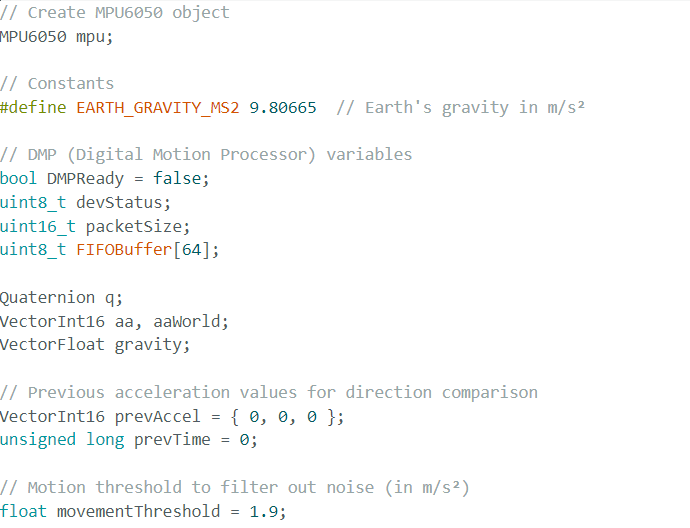
---> MPU6050 Object
MPU6050 mpu;- Creates an mpu object of class MPU6050, representing the MPU6050 sensor.
---> Constants and Flags
-
#define EARTH_GRAVITY_MS2 9.80665- Defines a constant for terrestrial gravity in m/s², used to convert raw acceleration values.
-
bool DMPReady = false;- A flag indicating whether the MPU6050's DMP (Digital Motion Processor) is ready and initialized.
---> DMP Configuration Variables
-
uint8_t devStatus;- Stores DMP initialization status.
-
uint16_t packetSize;- Stores the size of the DMP's FIFO data packet.
-
uint8_t FIFOBuffer[64];- A buffer to store the data read from the MPU6050's FIFO (First-In, First-Out).
---> Orientation and Motion Data**
-
Quaternion q;- A Quaternion object to store MPU6050 orientation data, representing rotation.
-
VectorInt16 aa, aaWorld;aa→ Stores the sensor's raw acceleration.aaWorld→ Stores the converted acceleration in a "world" reference frame (relative to gravity and absolute orientation).
-
VectorFloat gravity;- A VectorFloat object to store the calculated gravity vector.
---> Movement Detection Variables
-
VectorInt16 prevAccel = {0, 0, 0};- Stores previous acceleration values to compare changes in movement.
-
float movementThreshold = 1.9;- Defines the minimum acceleration change (in m/s²) considered a significant movement.
- Movements below this threshold are ignored, filtering out sensor noise.
---> Code Structure
The code is modularly structured and follows the Arduino environment's setup() and loop() functions.
It integrates advanced MPU6050 functionalities via its DMP and a dynamic display system on LCD and via the serial monitor.
Program Structure
The program is divided into two main parts:
---> void setup()
- Executed once at board startup.
- Initializes serial communication, configures the LCD screen, sets up the LED pins, and initializes the MPU6050 sensor, including its DMP configuration.
---> void loop()
- Executed continuously after
setup(). - Reads orientation data (quaternions, Euler angles) from the MPU6050 via DMP.
- Detects movements based on acceleration.
- Controls LEDs according to the detected movement.
- Displays information on the LCD and serial monitor.
void setup() – Initialization
---> I2C and Serial Communication
-
Wire.begin();&Wire.setClock(400000);- Initializes I2C communication.
- Sets the I2C clock speed to 400 kHz (fast mode) for faster data transfers.
-
Serial.begin(115200);- Initializes serial communication at 115200 baud.
- Used for debugging and displaying information on the serial monitor.
---> MPU6050 Initialization
-
mpu.initialize();&mpu.testConnection();- Initializes the MPU6050 and checks if the connection is established.
- If not, the program stops.
-
devStatus = mpu.dmpInitialize();- Initializes the MPU6050's DMP (Digital Motion Processor).
- The DMP performs complex calculations on sensor data, reducing the load on the microcontroller.
---> Sensor Calibration
mpu.setXGyroOffset(0);...mpu.setZAccelOffset(0);- Defines sensor calibration offsets.
- Initially set to zero, but can be adjusted after manual or automatic calibration.
---> DMP Initialization Check
if (devStatus == 0) {
    // DMP is ready
} else {
    // DMP initialization failed, program stops
}