1rst Test
Objectives
- Produce a batch of parts within a limited time frame while adhering to imposed constraints (materials, dimensions, etc.).
- Comply with a mass tolerance of ±5% for each manufactured part.
- Design sketches incorporating basic geometric shapes:
- Rectangles
- Circles
- Polygons
- Use extrusion and revolution features to model 3D parts based on the sketches.
- Evaluate the mass of each part.
Summary
Modeling files
Access the modeling files by clicking here.
Mass Summary of Part
| Part Number | Mass (g) |
|---|---|
| Part 1 | 2850.16 |
| Part 2 | 290.79 |
| Part 3 | 1633.25 |
| Part 4 | 112.37 |
Center of Gravity Analysis – Gripper
| Configuration | X (mm) | Y (mm) | Z (mm) |
|---|---|---|---|
| Fully Open | -29.15 | 0.16 | 19.86 |
| Fully Closed | -25.78 | 0.06 | 19.86 |
Materials
- Computer
- Internet connection
Execution
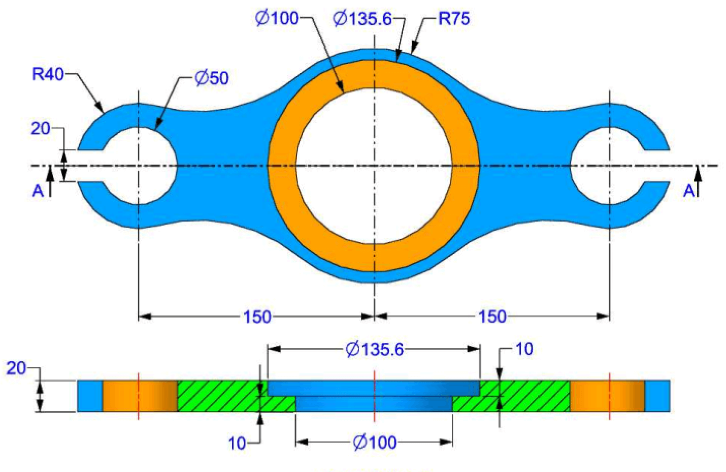
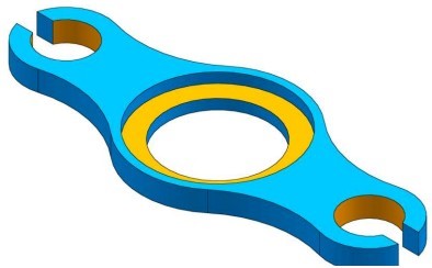
Modeling of the First Part
Unit Systems and Material Properties
- Unit System: MMGS (Millimeter, Gram, Second)
- Decimals: 2
- Hole Specification: All holes are through unless otherwise specified
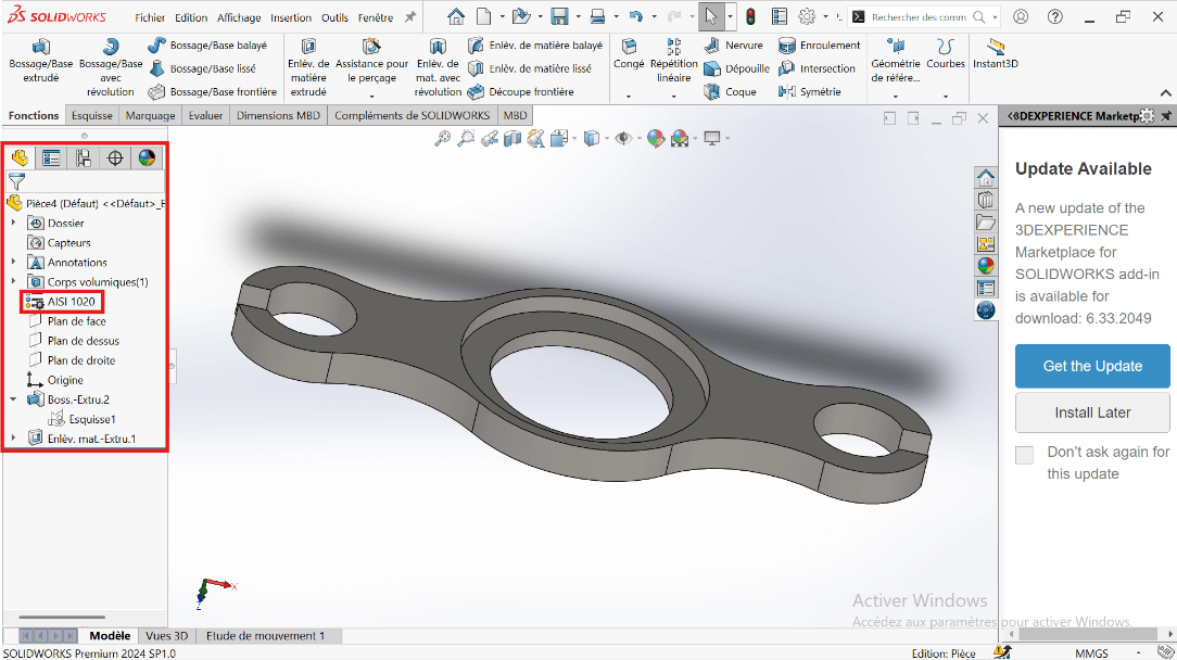
- Material: AISI 1020 Steel
- Density: 0.0079 g/mm³
Process of Obtaining the Part
--> 1. Workspace Setup
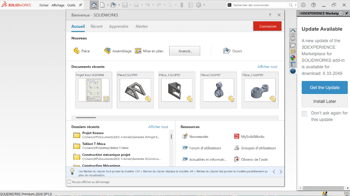
- Launch SolidWorks and select New Part.
- Click on Piece to start modeling a new piece.
- In the design tree, right-click the Front Plane and choose Edit Sketch.
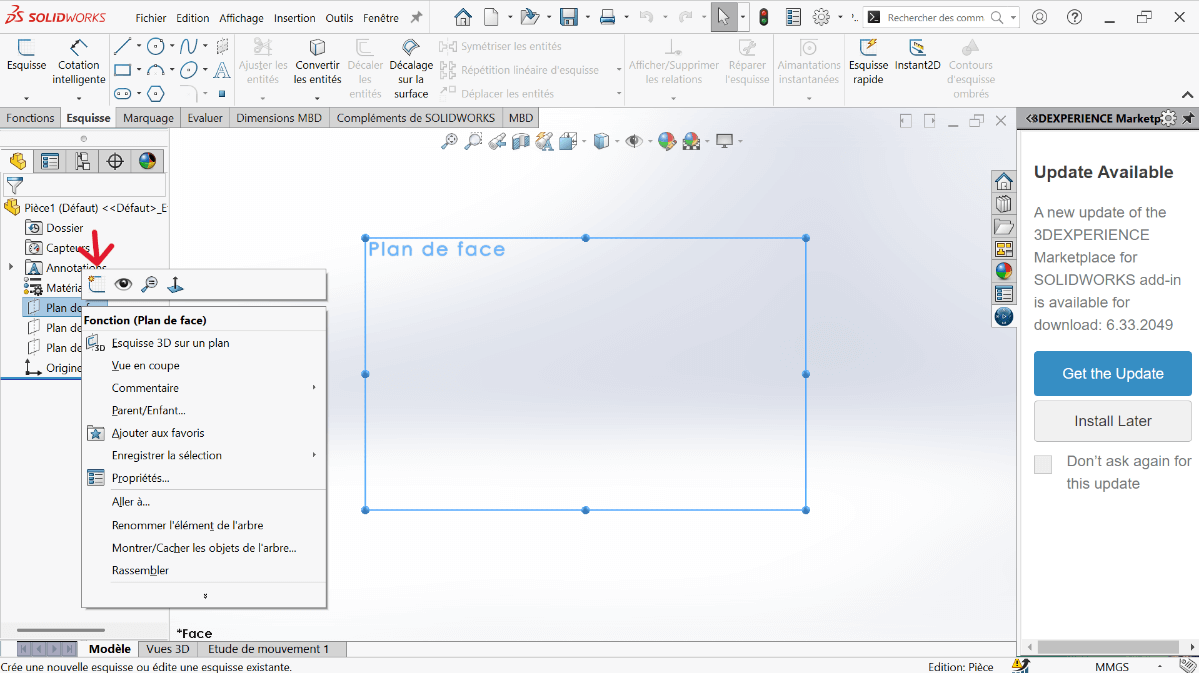
- Set the unit system to MMGS (Millimeter, Gram, Second).
- Ensure decimals are set to 2.
- Assume all holes are through unless stated otherwise.
- Assign material as AISI 1020 Steel with a density of 0.0079 g/mm³.
--> 2. Sketching the Base Profile
---> a. Create Centerlines
- Click on the Line function.
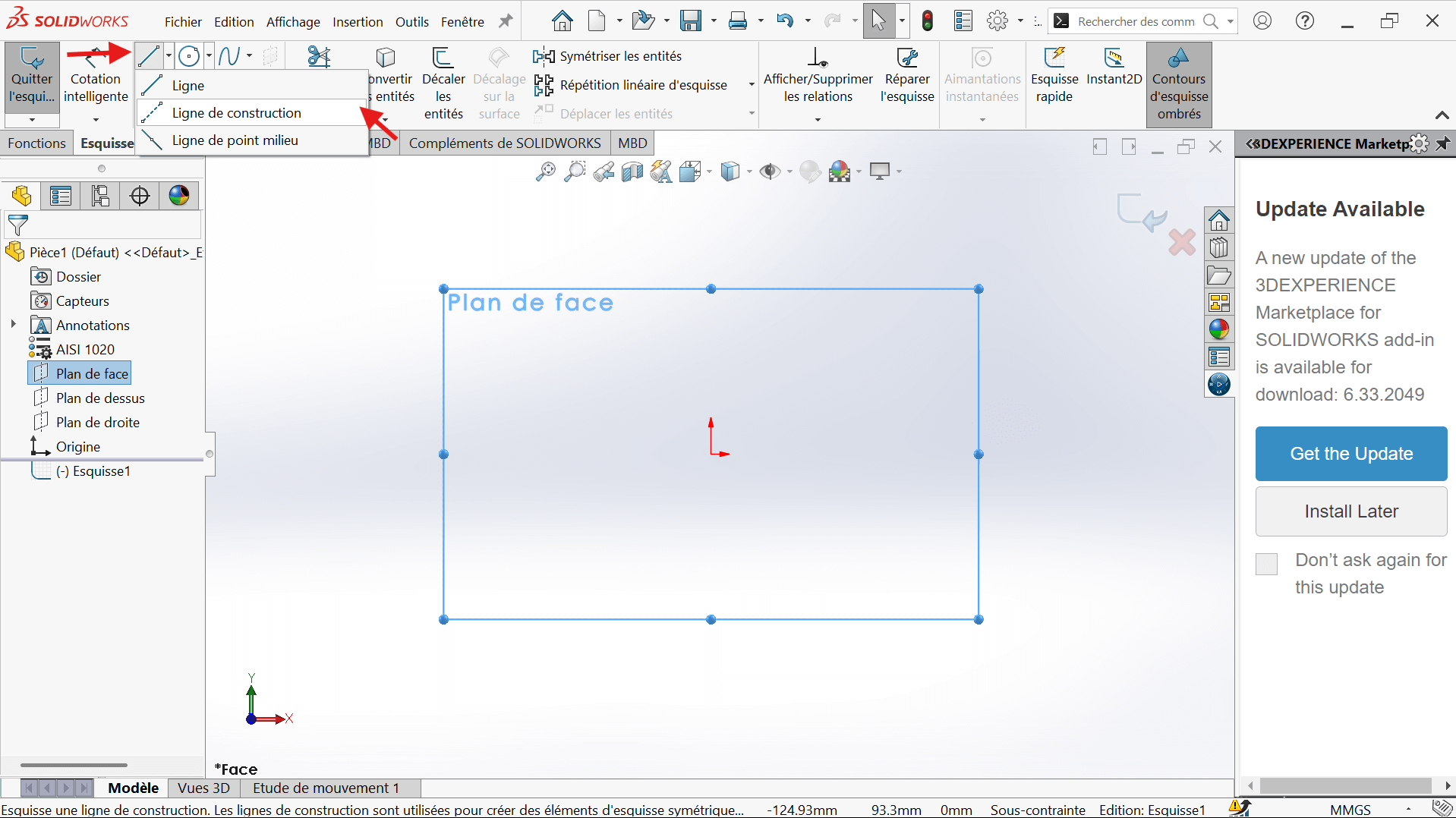
- Select the Horizontal Constraint and For Construction in the properties.
- Position the start and end points, ensuring alignment with the reference frame.
- Click Validate to confirm.
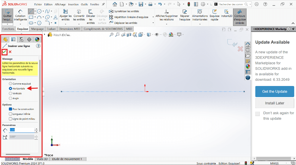
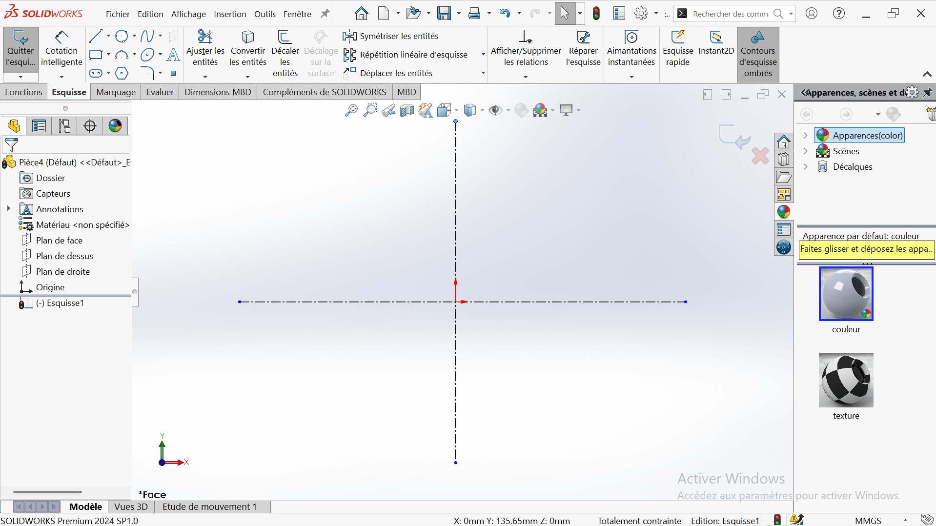
- Click again on the Vertical Constraint to draw the vertical axis, ensuring alignment with the reference frame.
- Click Validate to confirm.
---> b. Draw Concentric Circles
- In the top ribbon, click on "Circle".
- Click on the intersection point of the two axes (center of the circle).
- Stretch the circle to any size for now.
- Enter the circle radius in the properties panel on the left.
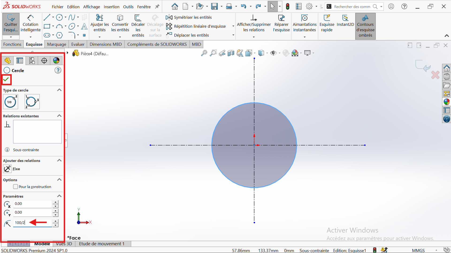
- Select the "Smart Dimension" tool.
- Click on the edge of the circle → a diameter dimension will appear.
- Enter the value 100 mm (since the radius is 50 mm, the diameter is 100 mm).
- Click Validate to confirm.
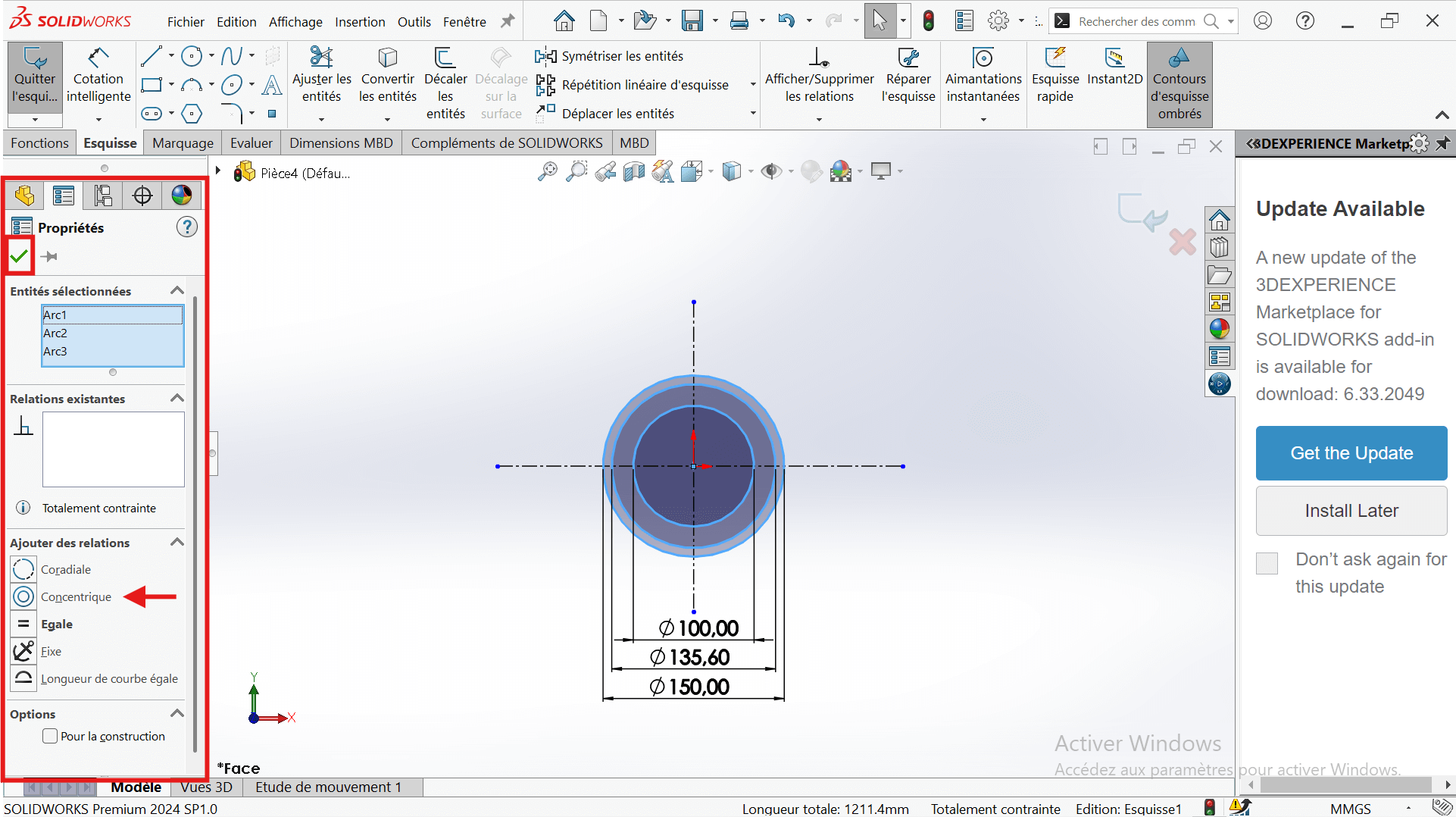
- Draw two other circles centered on the origin:
- Diameter 135.6 mm
- Diameter 150 mm
- Apply concentricity constraints to ensure a common center.
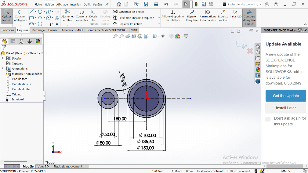
---> c. Add Offset Circle
- Create a new circle on the horizontal axis, offset from the origin.
- Set its diameter to 80 mm (radius = 40 mm).
- Use Smart Dimension to set the center-to-center distance from the 150 mm circle to 150 mm.
---> d. Add Additional Circle
- Draw another circle with a diameter of 50 mm, concentric with the 80 mm circle.

--> 3. Creating Fillet and Cutout
---> a. Create Tangent Arc
- Use the Perimeter Circle to draw a circle tangent to the 150 mm and 80 mm circles.
- Set the appropriate diameter to represent a 75 mm fillet.
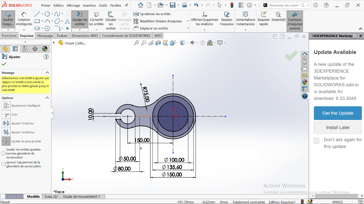
- Use the Trim Entities tool to remove excess lines, forming a closed contour.

---> b. Offset the Arc
- Select the arc and apply a 10 mm offset using Offset Entities.
- Trim intersecting entities to clean up the sketch.
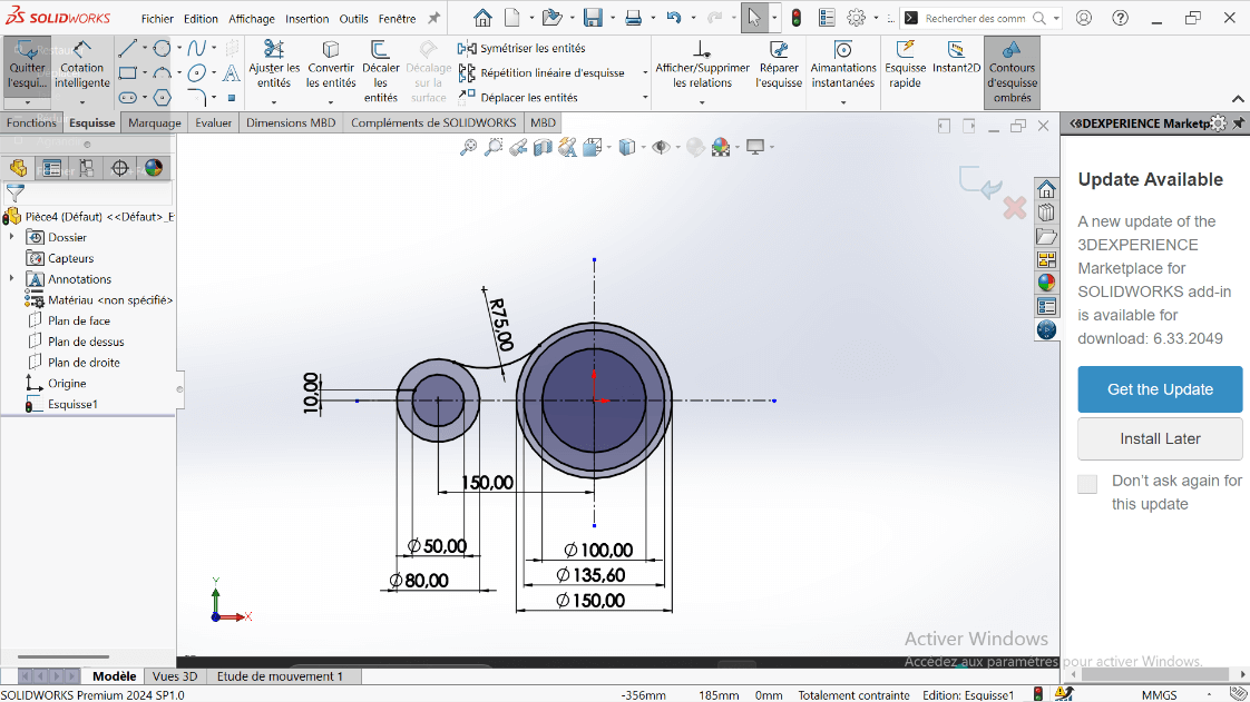
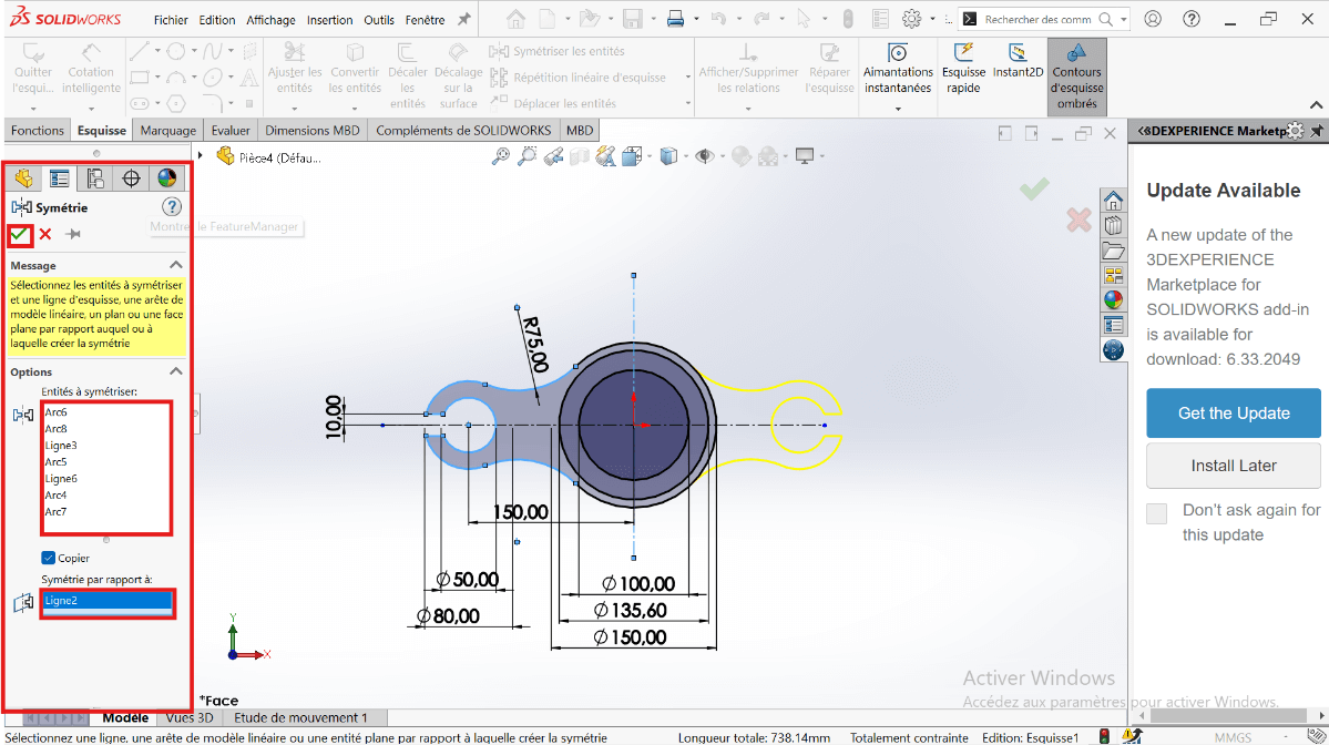
---> c. Mirror the Cutout
- Use Mirror Entities to duplicate the feature across the horizontal axis.
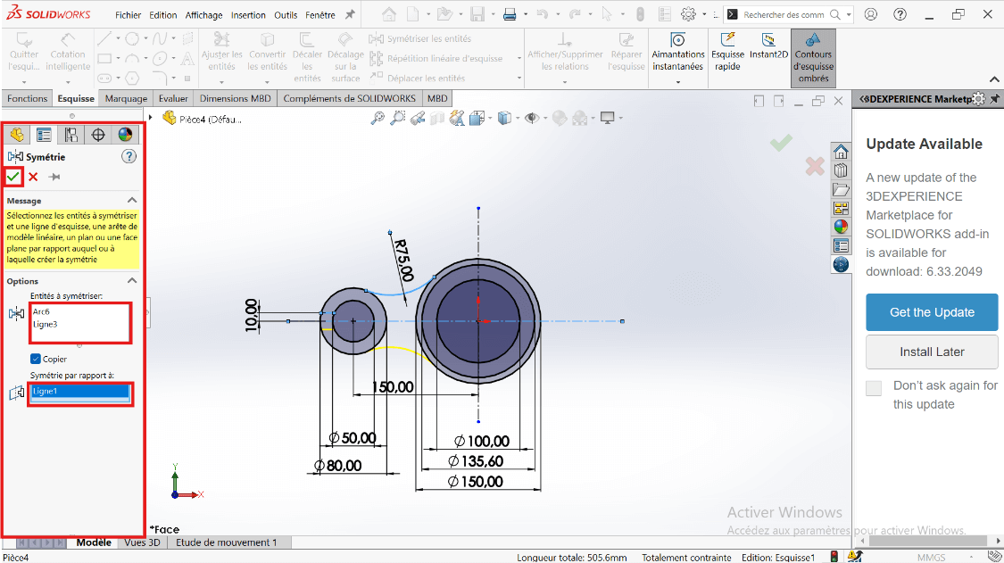
- Then mirror the resulting shapes across the vertical axis for full symmetry.
 .
.
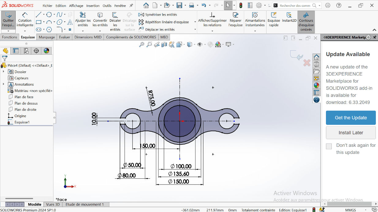
- Ensure the sketch forms a closed loop.
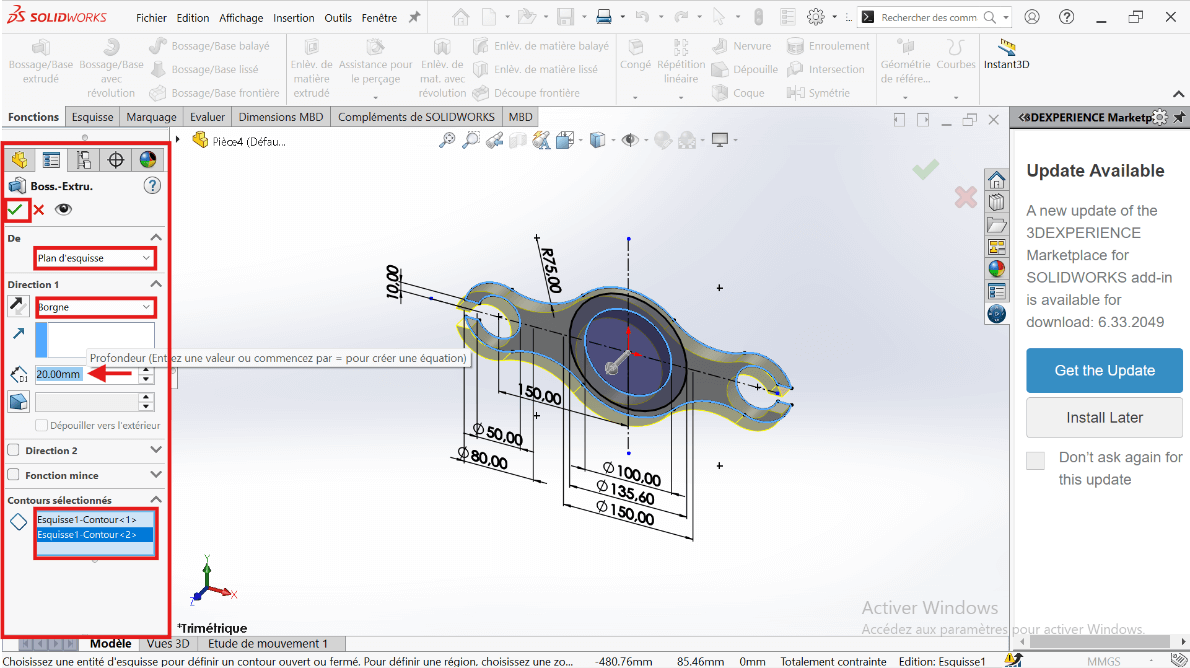
--> Creating the 3D Volume
-
Exit the sketch and switch to the Features tab.
-
Use Extruded Boss/Base:
- Select the entire sketch.
- Choose Blind extrusion with a depth of 20 mm.
- Select only the 100 mm diameter region to extrude the solid part.
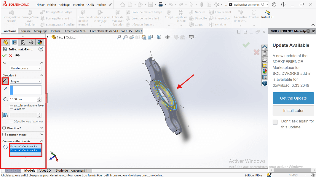
--> 5. Adding the Cut (Counterbore)
- Use Extruded Cut on the same sketch:
- Set cut depth to 10 mm.
- Select the region between 100 mm and 135.6 mm circles as the cut profile.
--> 6. Mass Evaluation
- Type Mass in the search bar.
- Click on Mass Properties.
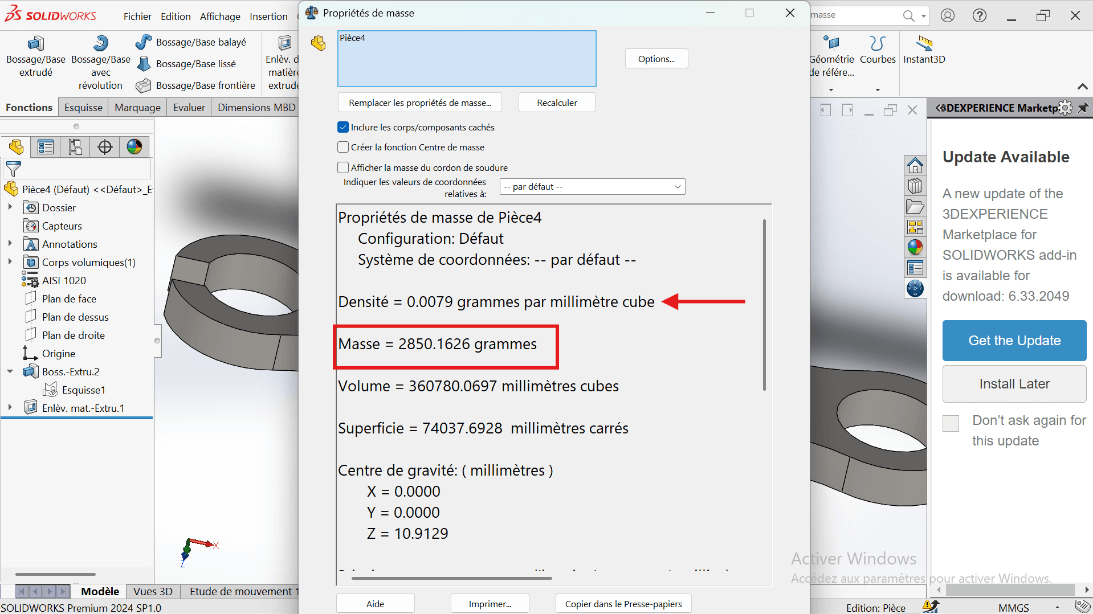
The part mass should be 2850.16 grams.
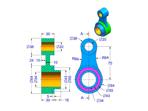
Modeling of the Second Part
Unit Systems and Material Properties
- MMGS (Millimeter, Gram, Second)
- Decimals: 2
- Hole Specification: All holes are through unless otherwise specified
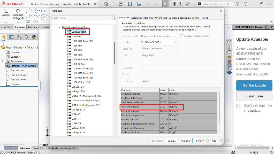
- Material: Aluminum Alloy 1060
- Density: 0.0027 g/mm³
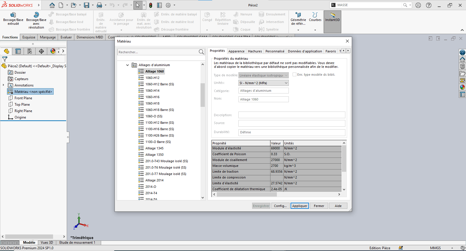
--> 1. Modifying Part 2 Parameters
- Right-click on Material: "Not Specified".
- Click on Edit Material.
- The Material tab opens.
- Navigate to SolidWorks Materials → Aluminum Alloy → Alloy 1060.
- Click Apply and Close.
--> 2. Preparing the Workspace
- Click on Front Plane.

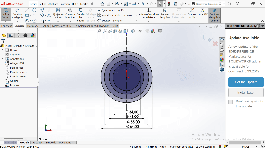
--> 3. Sketch Creation
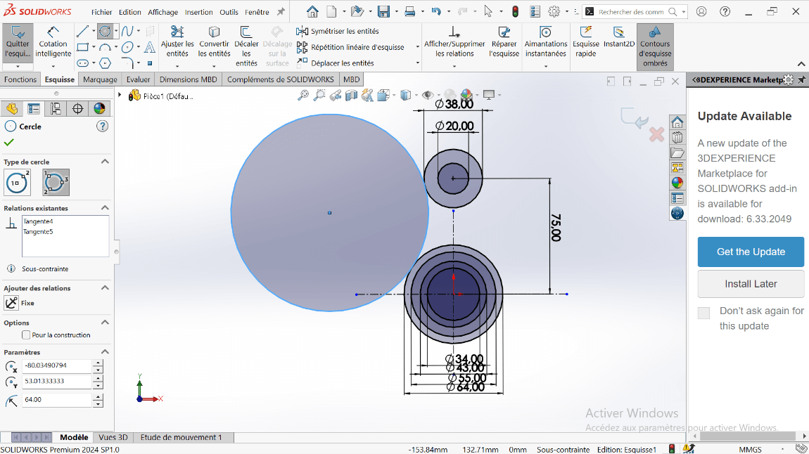
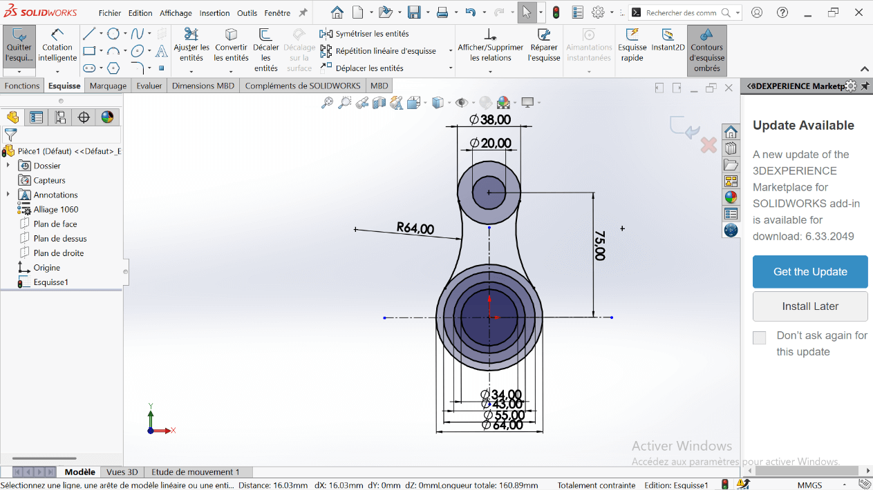
- Click on the Circle tool and draw concentric circles with diameters 20 mm and 38 mm, centered on the vertical axis.
- Click on Smart Dimension:
- Select the 64 mm and 38 mm diameter circles.
- Specify the center distance as 75 mm and validate.
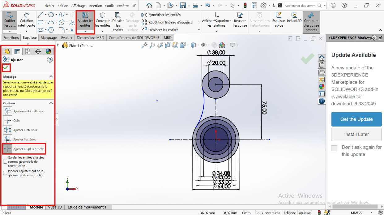
- Right-click on the Circle tool and select Perimeter Circle.
- Select the entities:
- Click on the 64 mm and 38 mm diameter circles.
- Click on an external point (the created circle will be tangent to the selected circles).
- Specify the fillet radius as R64.
- Click on the Trim Entities tool to remove overlapping sketch parts and create a closed sketch.
- Select the Trim tool properties.
- Click on the entities to remove.
- Apply the dimensioning to the fillet.
- Click on the Symmetry tool.
- Select the entities to symmetrize: R64 fillet.
- Select the symmetry axis: Vertical axis.
--> 3. Creating the Volume
- Click on Features → Extruded Boss/Base.
- Select the entities to extrude.
- Click Validate.
- Click on Boss/Base → Sketch.
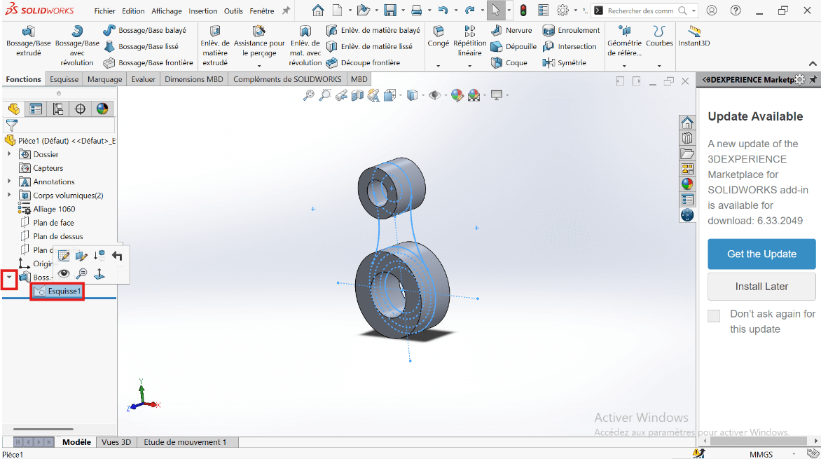
- Click on Features → Extruded Boss/Base.
- Select the entities to extrude.
- Click Validate.
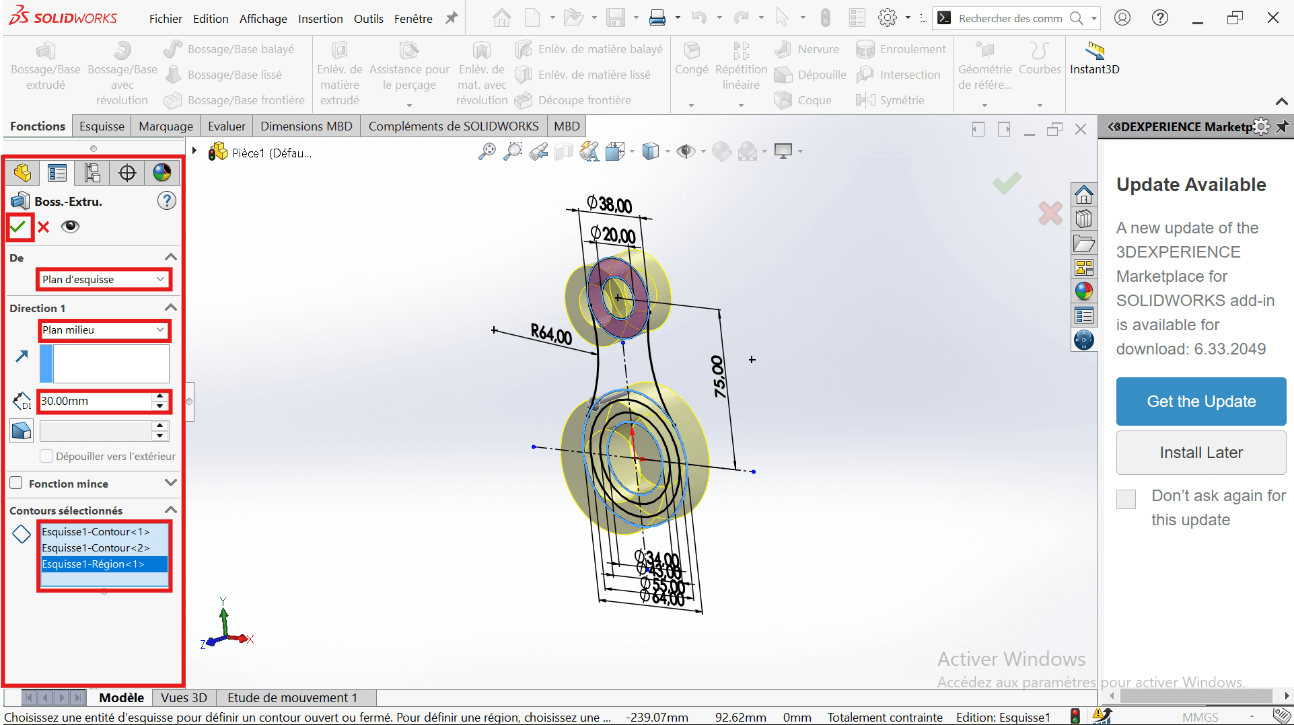
- Click on Boss/Base → Sketch → Extruded Boss/Base.
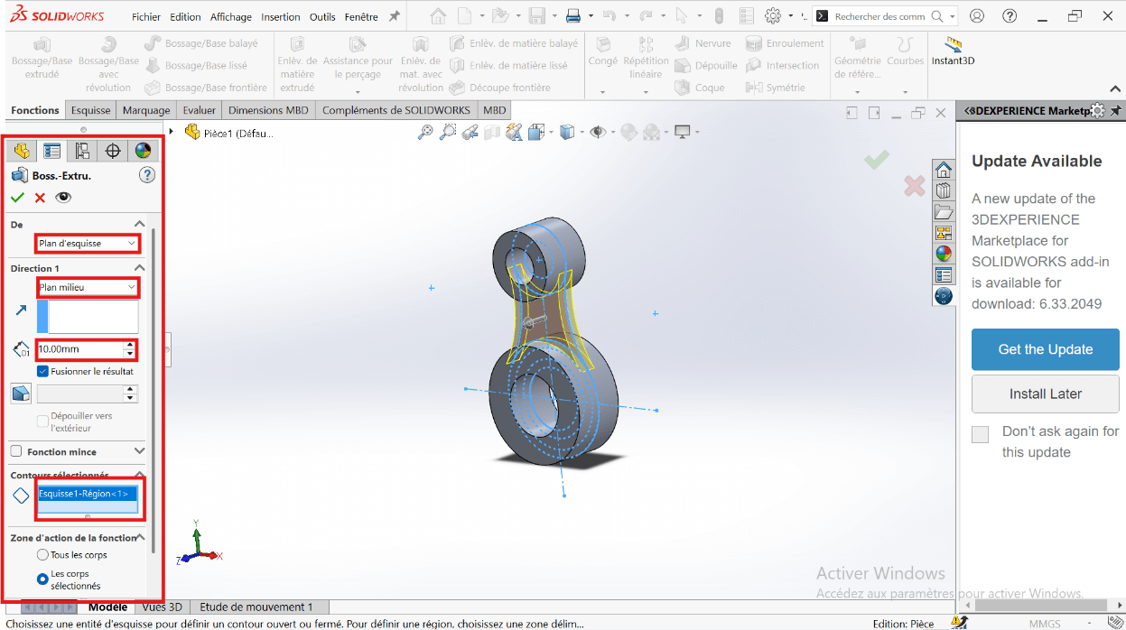
- Select the entities to extrude: 43 mm and 34 mm diameter circles.
- In the parameters, select Direction 1 and Direction 2.
- Specify the extrusion distances: 15 mm and 30 mm.
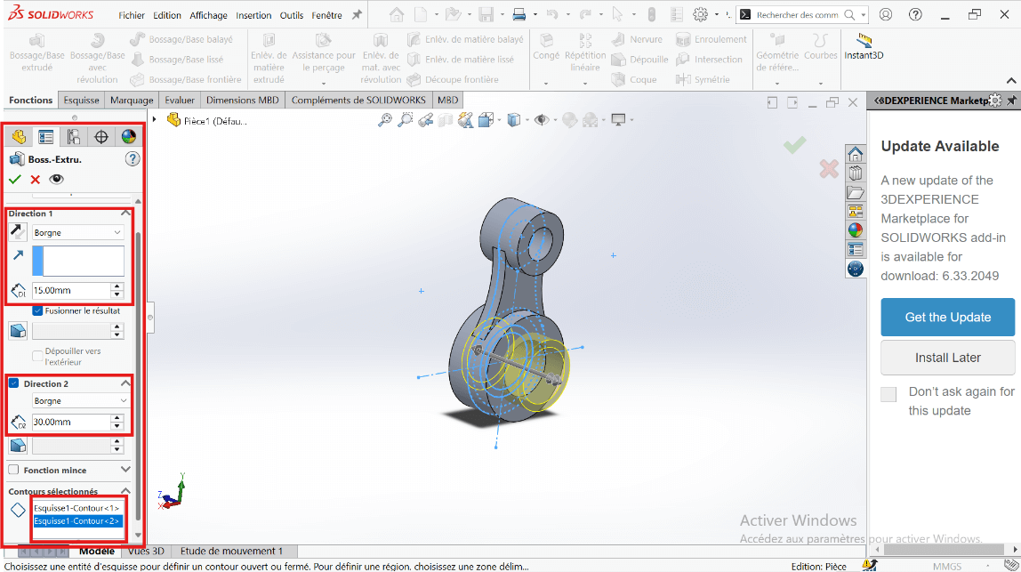
- Click Validate.
- Click on Boss/Base → Sketch → Extruded Cut.
- Select the entities to cut: 43 mm and 55 mm diameter circles.
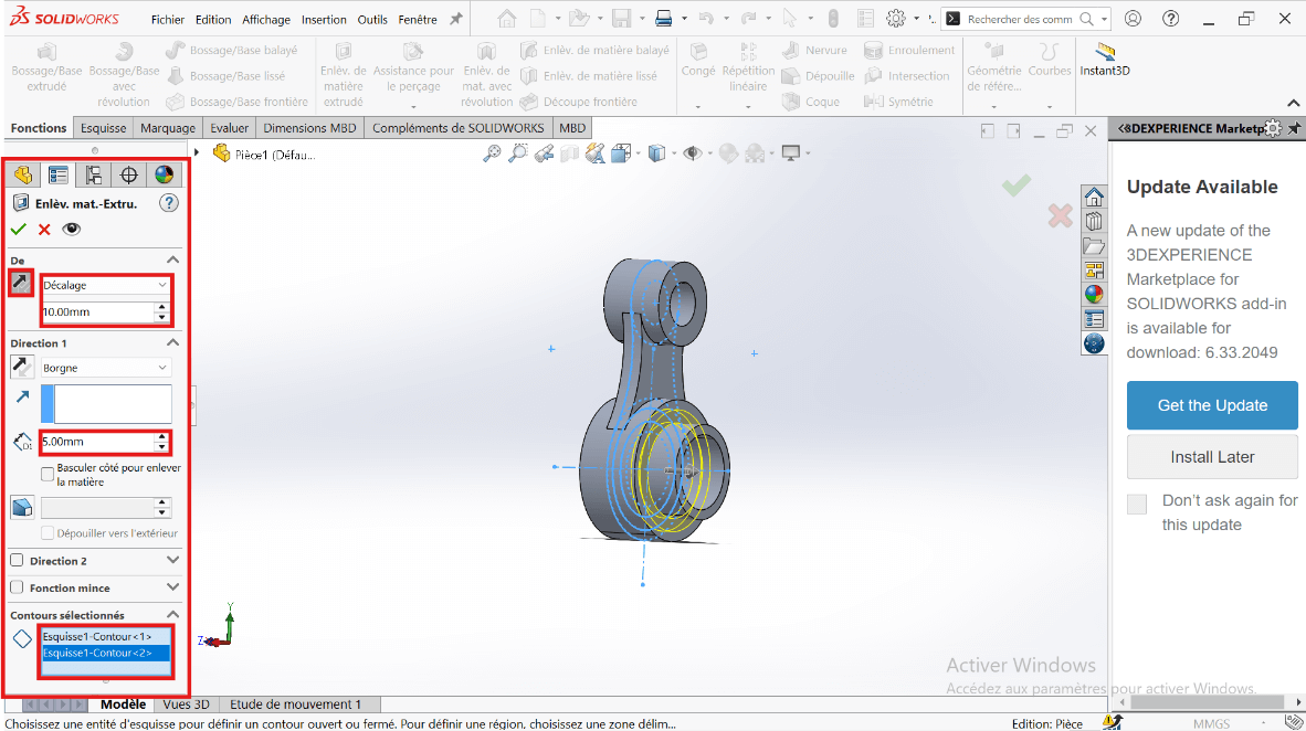
- Click Validate.
--> 6. Mass Properties
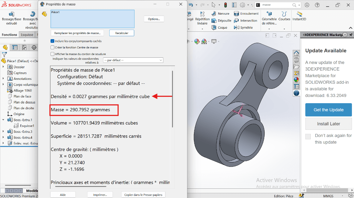
- Mass Calculation: Use the Mass Properties tool to determine the part's mass.
The part mass is : 290.79 gramms
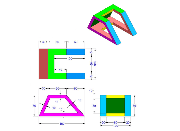
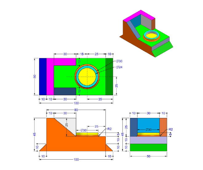
Modeling of the Third Piece
Unit System
- MMGS (Millimeter, Gram, Second)
- Decimals: 2
- Hole Specification: All holes are through unless otherwise specified
- Material: AISI 1020 Steel
- Density: 0.0079 g/mm³
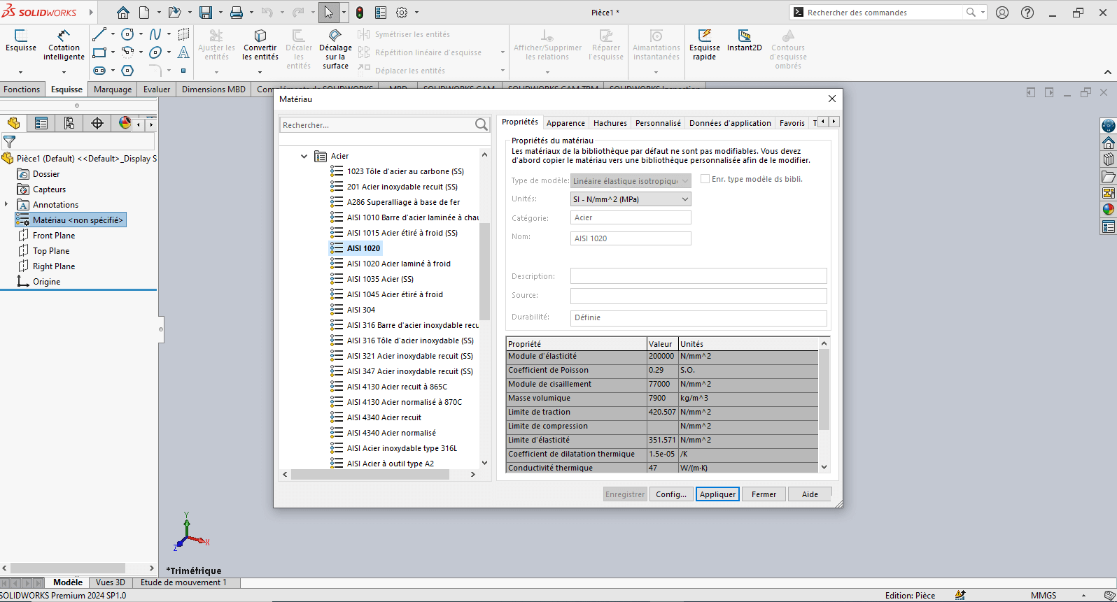
--> 1. Modifying Part 3 Parameters
-
Right-click on Material: "Not Specified"
-
Select Edit Material
-
In the Material tab:
- Browse to SolidWorks Materials > Steel > AISI 1020
- Click Apply, then Close
-
Click on the Front Plane, then select Sketch
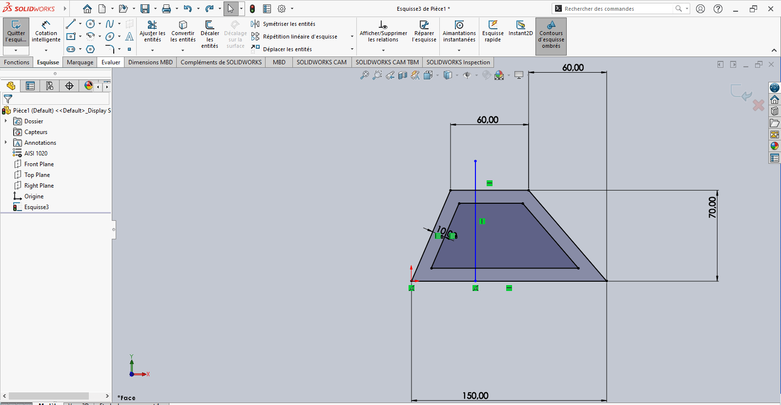
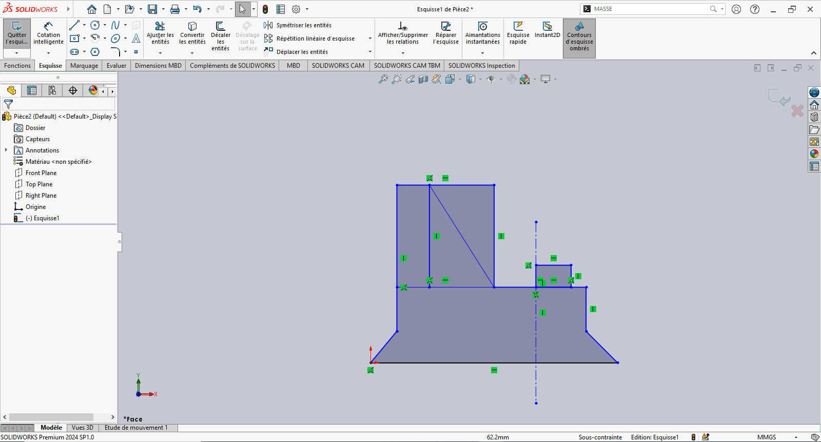
--> 2. Creating the Sketch
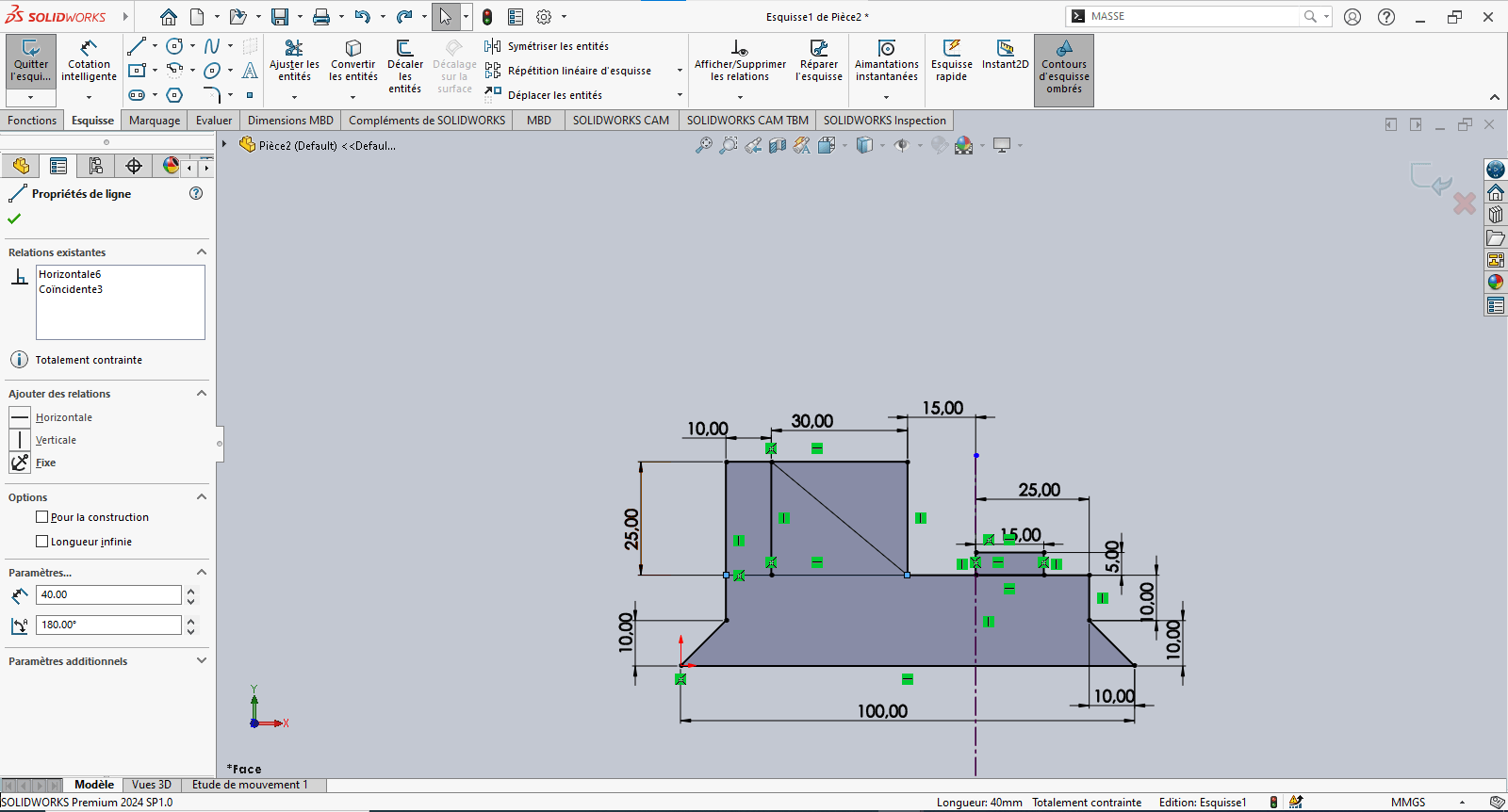
- Use the Line tool to draw a trapezoid (initial dimensions can be arbitrary)
- Use Smart Dimensioning to set precise dimensions
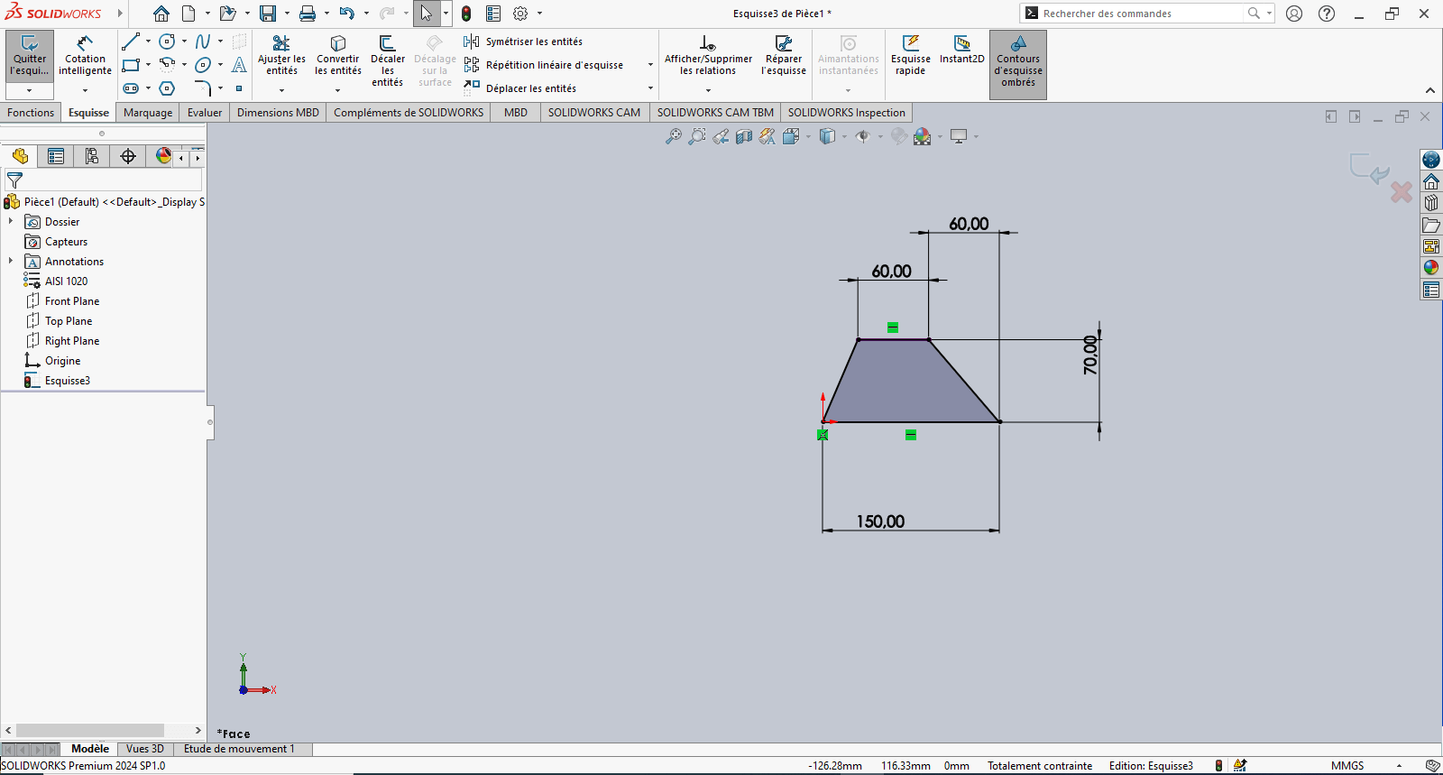
Tip: Reference the origin to fix the sketch and improve stability
- Use the Offset Entities tool to offset the trapezoid 10 mm inward
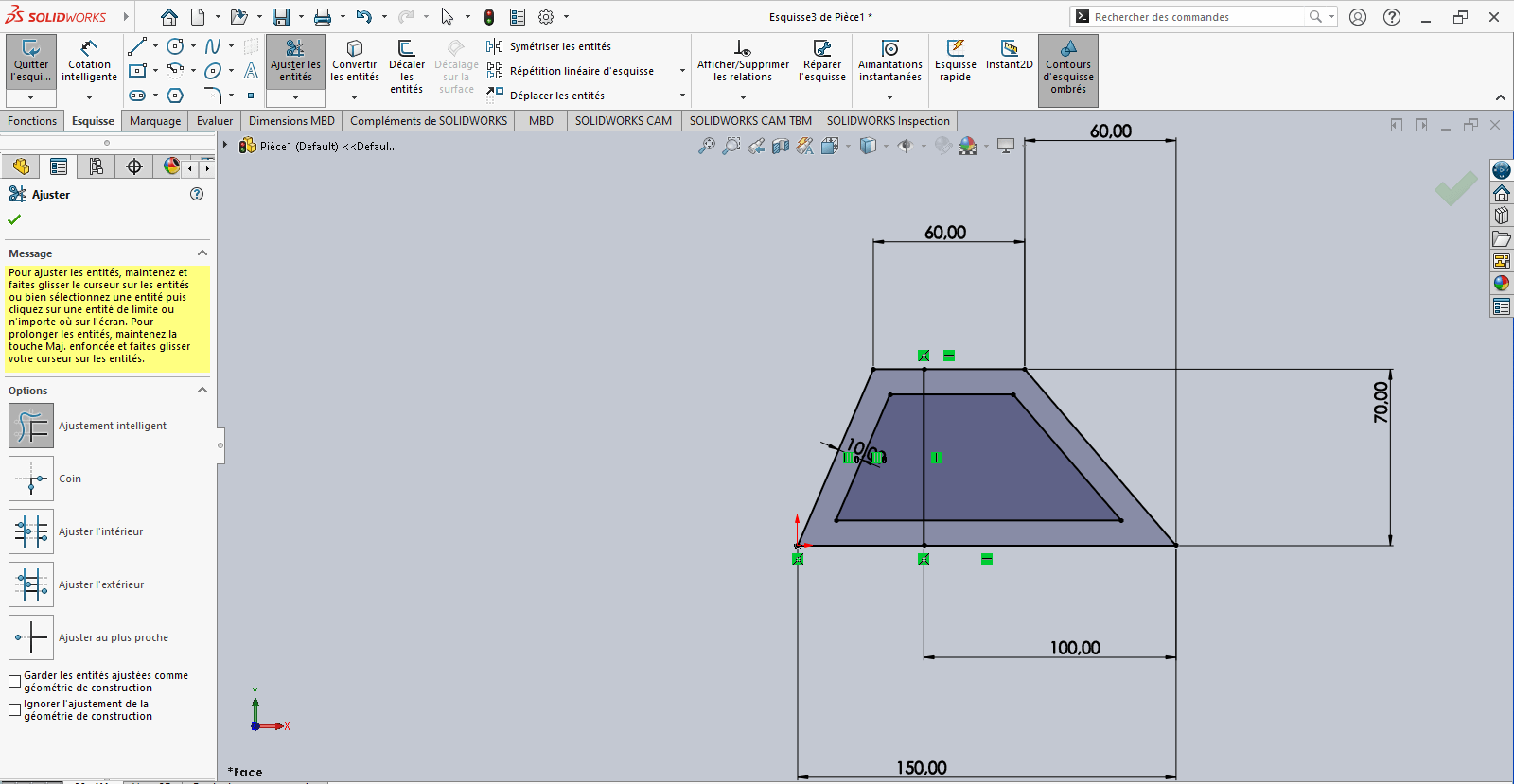
-
If the offset direction is incorrect, reverse it in the Property Manager
-
Use the Line tool again to draw a vertical line starting from the base of the 150 mm horizontal segment
- Apply Smart Dimensioning to position this line relative to a fixed reference point
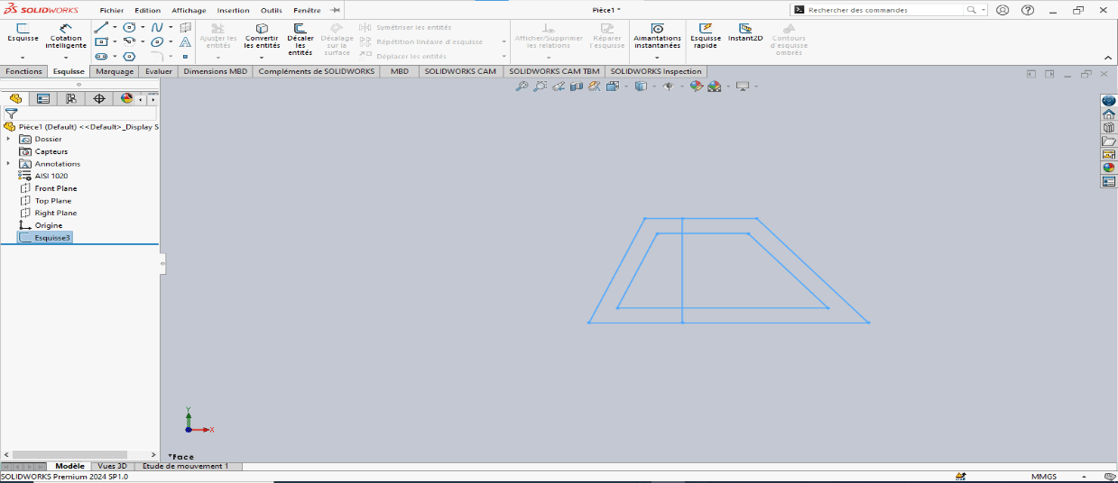
- Verify that the sketch is fully constrained
- If not, apply necessary constraints to stabilize the geometry
- Exit the sketch
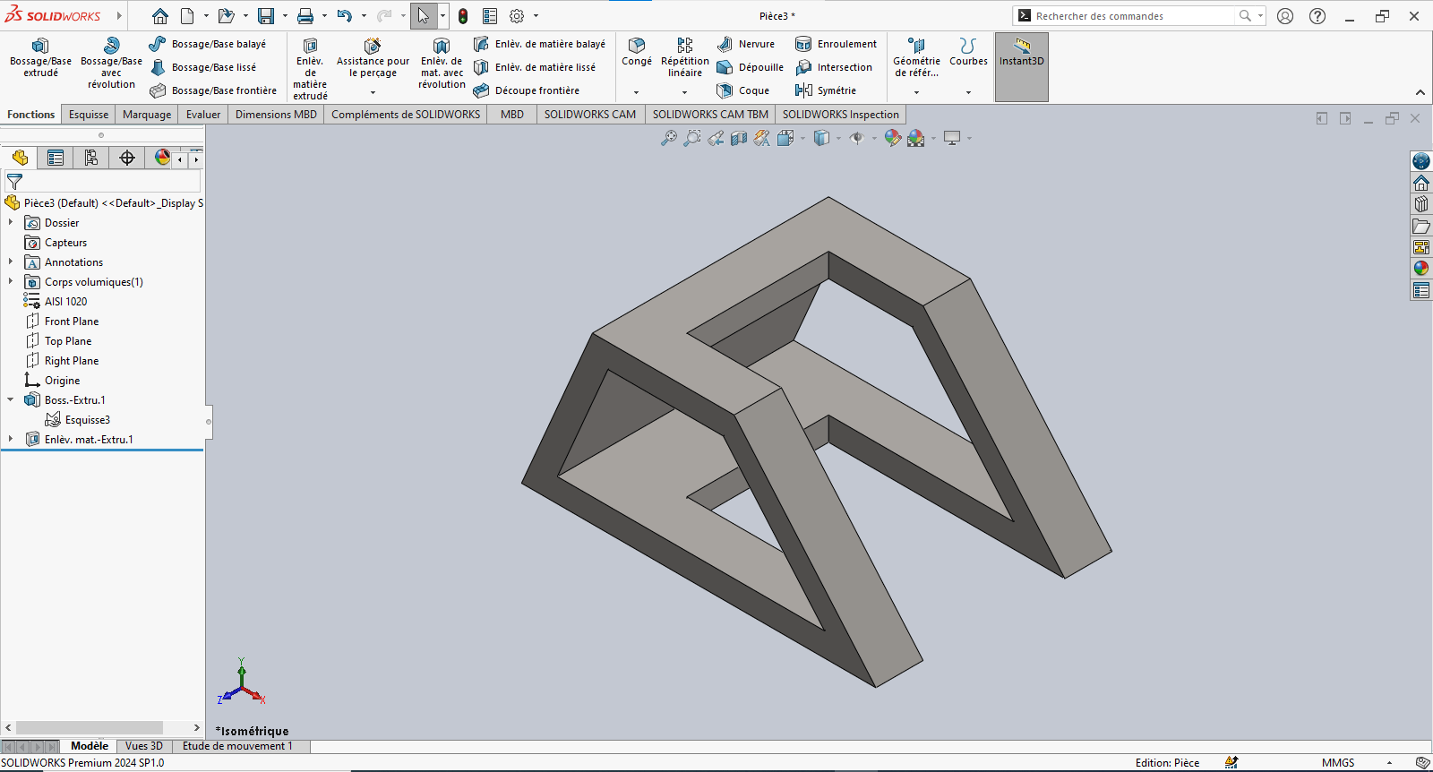
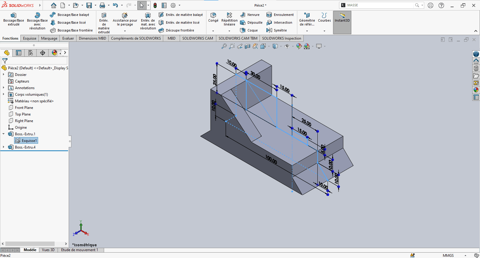
--> 3. Creating the 3D Volume
---> Boss-Extrude (Solid)
-
Navigate to Features > Extruded Boss/Base
-
Select the sketch entities to extrude
-
Set extrusion properties:
- Direction: Select Mid Plane
- Depth: 100 mm
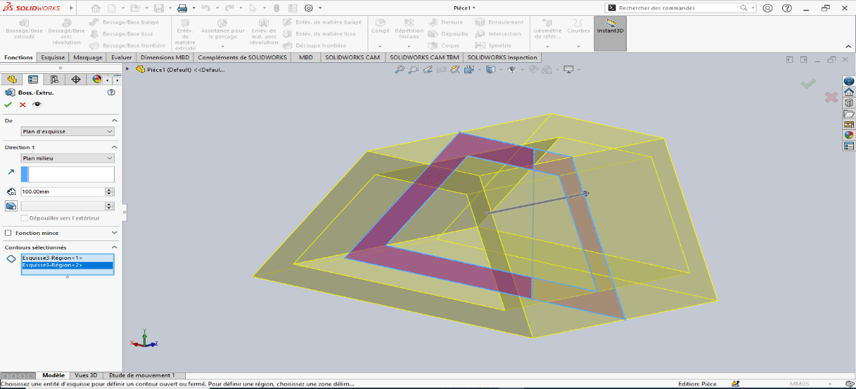
-
Confirm by clicking OK
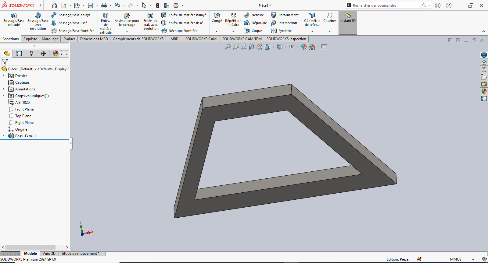
---> Cut-Extrude (Material Removal)
-
Select Extruded Cut
-
Choose the entities to remove
-
Set extrusion properties:
- Direction: Select Mid Plane
- Depth: 60 mm
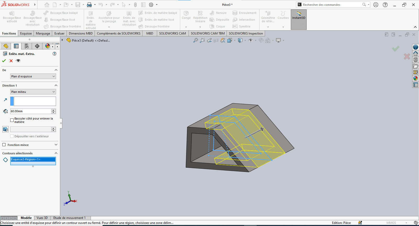
-
Confirm by clicking OK
--> 4. Evaluating Part Mass
- Type "Mass" in the search bar
- Click on Mass Properties
- Review the calculated mass based on geometry and material assignment

The piece mass is : 1633.25 gramms
Modeling of the Fourth Piece
Unit System
- MMGS (Millimeter, Gram, Second)
- Decimals: 2
- Hole Specification: All holes are through unless otherwise specified
- Material: Aluminum Alloy 1060
- Density: 0.0027 g/mm³
--> 1. Updating Material Settings
- Right-click on Material: “Not Specified”
- Select Edit Material
- In the Material tab:
- Navigate to SolidWorks Materials > Aluminum Alloys > 1060 Alloy
- Click Apply, then Close
--> 2. Preparing the Workspace
- Select the Front Plane and click Sketch
--> 3. Creating the Sketch
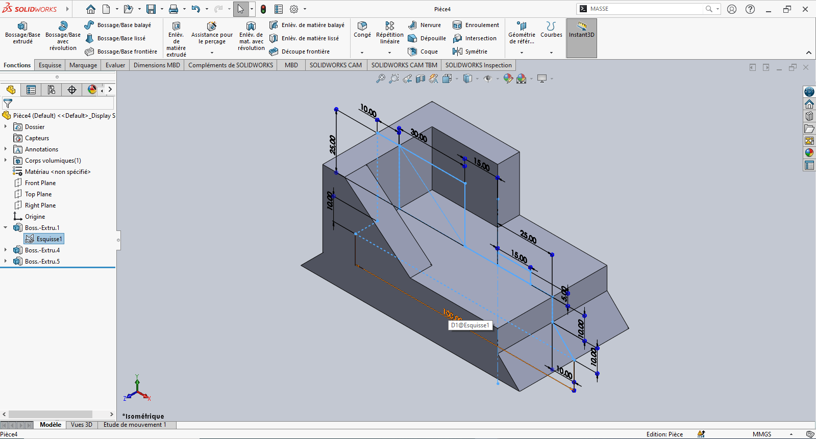
- Use the Line tool to draw a profile similar to the front view of the part
- Use Smart Dimension to assign dimensions to the sketch elements
- Reference the origin wherever possible for stability
- Exit the sketch
--> 4. Creating the Volume – Extrusions
---> First Extrusion
- Click Features > Extruded Boss/Base
- In the Feature Manager:
- Set extrusion direction to Mid Plane
- Set Depth to 50 mm
- Select the appropriate contour and confirm

---> Second Extrusion
-
Return to the same sketch
-
Click Extruded Boss/Base
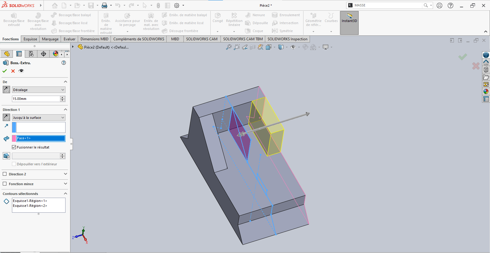
- Set an offset of 15 mm
- Define the direction carefully (flip if needed)
- Choose Up to Surface as the end condition if required, and select the target face
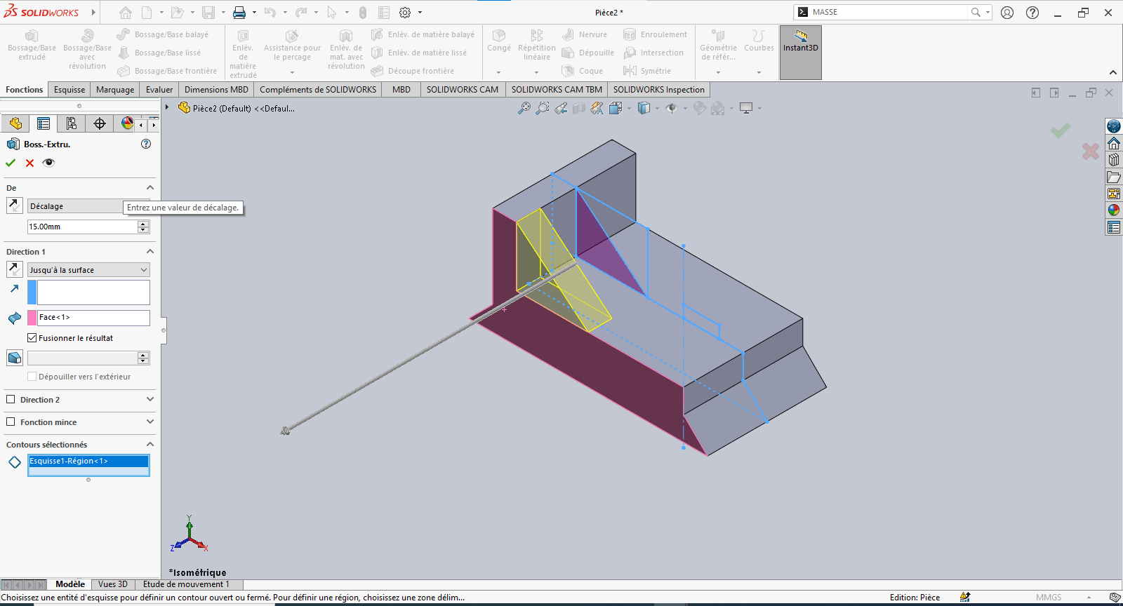
-
Validate the extrusion
---> Third Extrusion
-
Repeat the previous step
- Again, pay attention to offset direction
- Use Up to Surface for precise alignment
-
Confirm the operation
--> 5. Revolved Feature
-
In the sketch, select Revolved Boss/Base
- Specify the revolution angle
- Select the profile to revolve
- Choose the axis of revolution
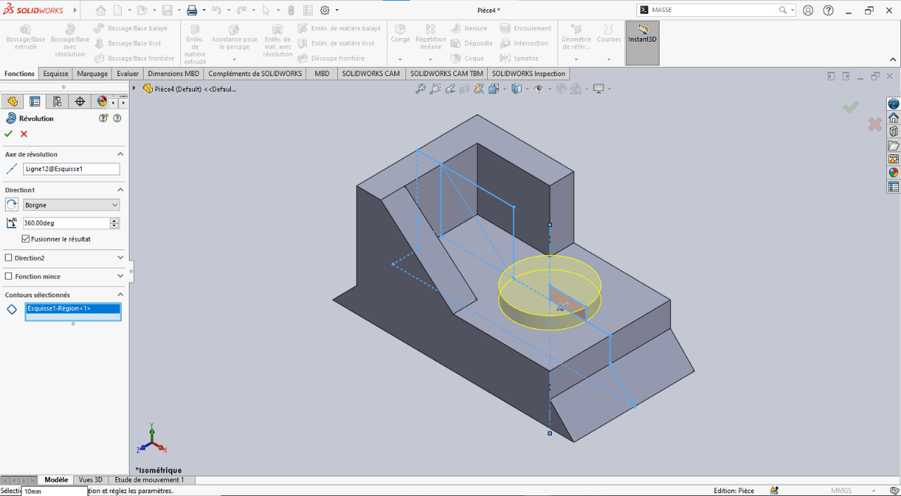
-
Confirm the feature
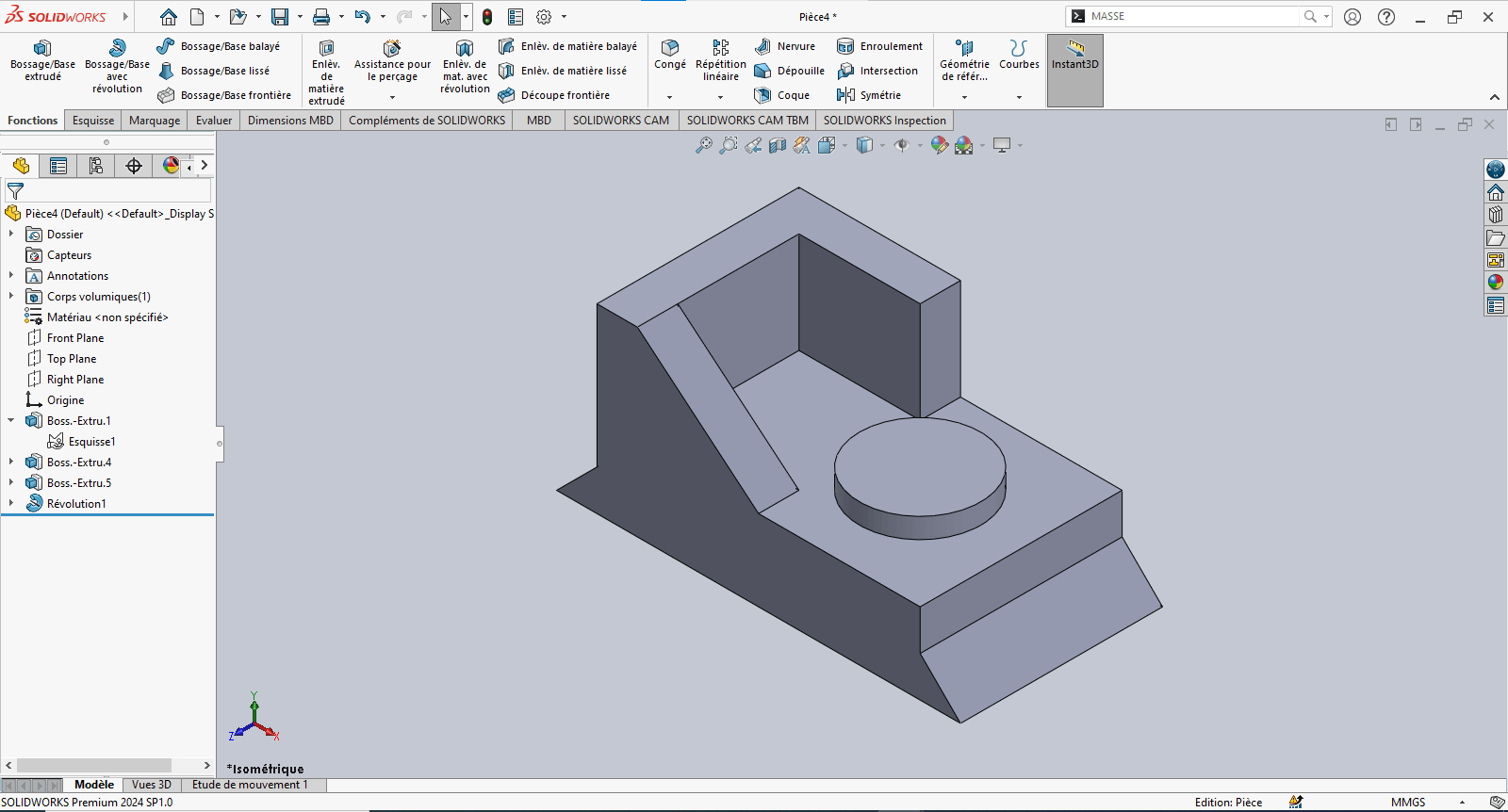
--> 6. Adding Fillets
- Use the Fillet tool to apply a 2 mm radius to the designated edge(s)
- Validate the fillet
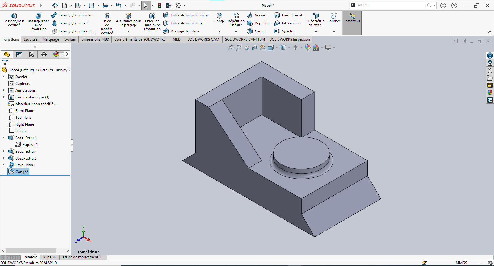
--> 7. Evaluating the Part's Mass
- Type "Mass" in the search bar
- Click on Mass Properties
- Review the calculated mass value
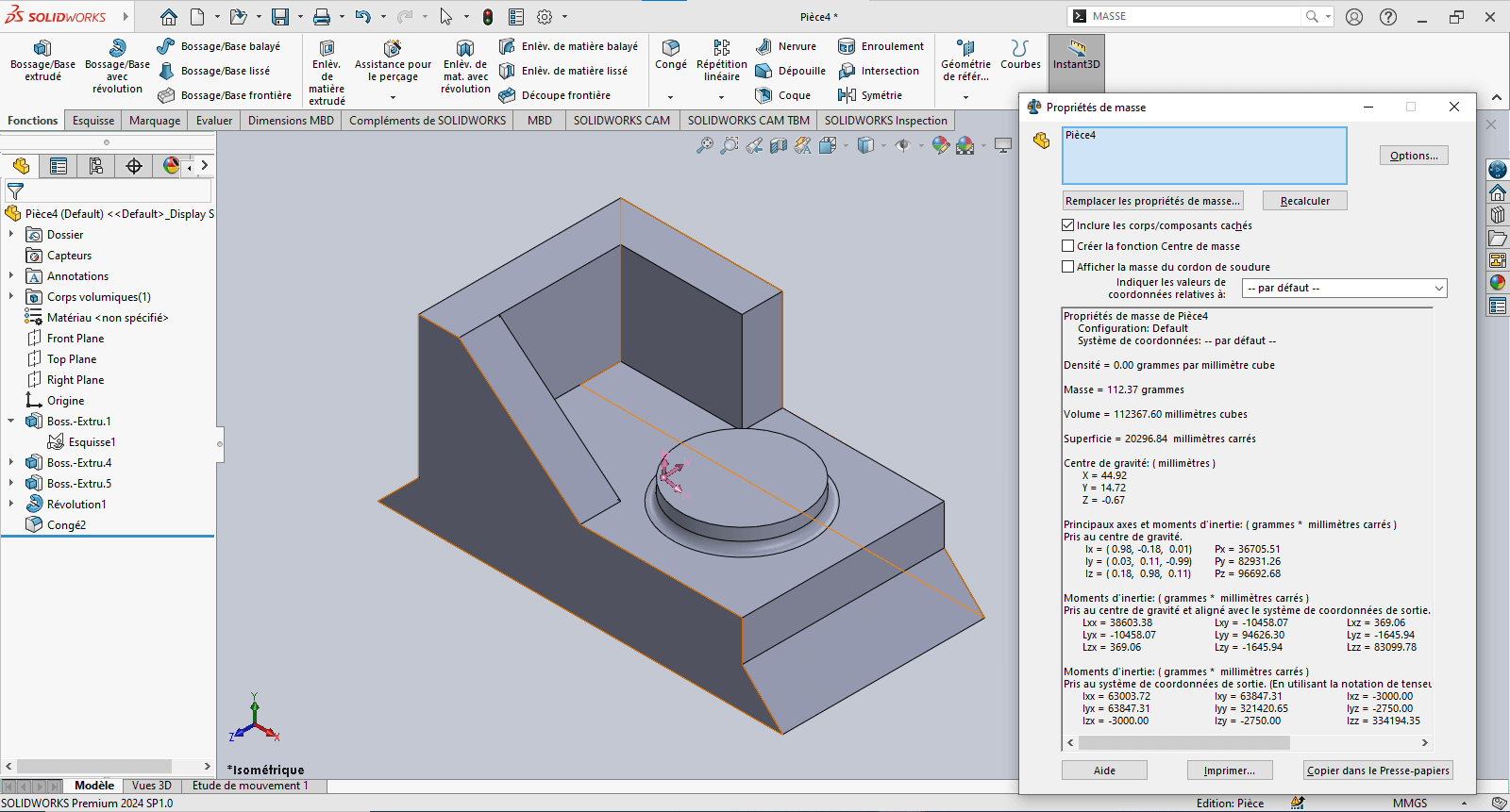
The piece mass is : 112.37 gramms
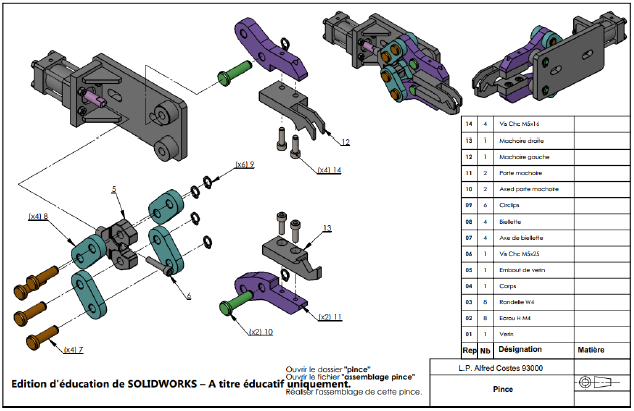
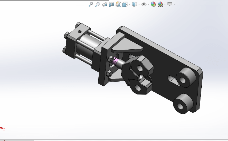
Assembly – Mechanical Gripper
Objective
This stage of the test involves assembling various components to form a mechanical gripper. After downloading the provided .zip file, the goal is to assemble the given parts using appropriate constraints.

Constraints and Functions Used in the Gripper Assembly
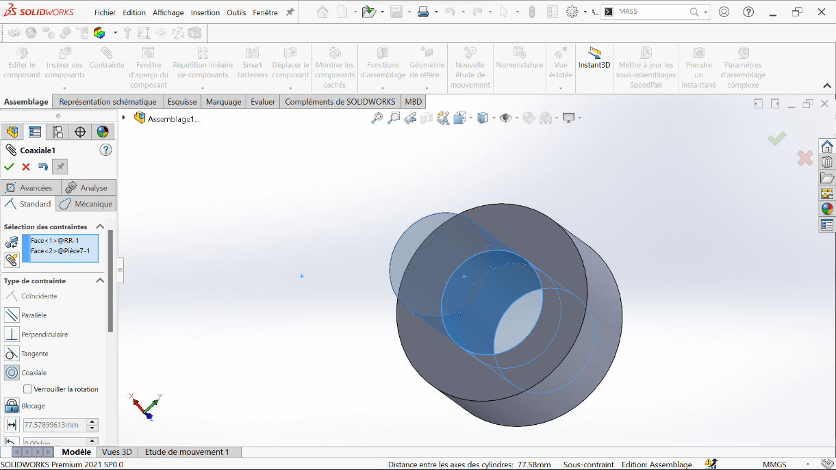
--> 1. Coaxial Constraint
This constraint aligns two cylindrical or circular axes (holes, shafts, cylinders) to share the same center axis.
Example: Aligning a shaft with its corresponding hole ensures proper axial alignment.
--> 2. Coincident Constraint
This constraint forces two planar or linear surfaces to touch, making them coplanar or flush.
Usage: Used to attach one part directly against another.
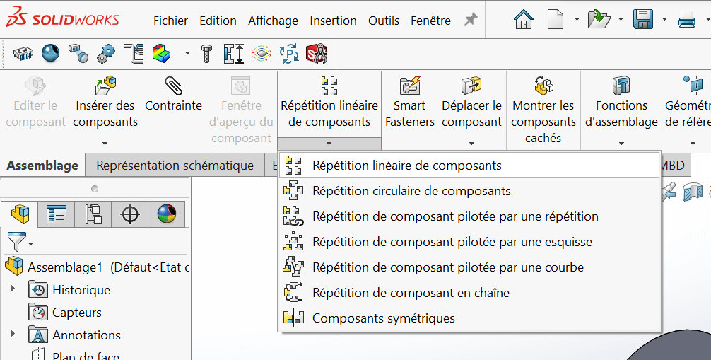
--> 3. Symmetric Components Function Under the Linear Component Pattern feature, this function generates a mirrored component from a parent part across a defined reference plane.
Assembly Steps
- Open SolidWorks, then open the file
ASSEMBLAGE PINCE.
- Insert the following parts to complete the mechanical gripper:
- Connecting Links (Biellettes)
- Jaw Holders (Porte Mâchoire)
- Left and Right Jaws (Mâchoire Gauche & Droite)
- Link Axles (Axe de Biellette)
- Jaw Holder Axles (Axe Porte Mâchoire)
- M5×16 Screws
- M5×25 Screws
- Circlips
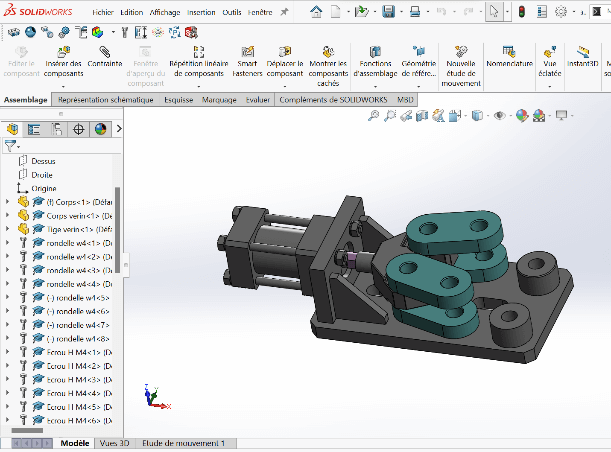
Positioning the First Link
- Insert the first biellette (link)
- Apply Coaxial and Coincident constraints to mount it on top of the cylinder rod end
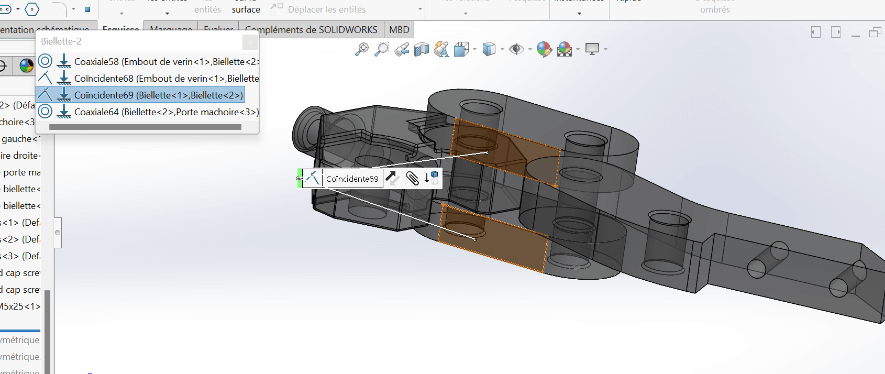
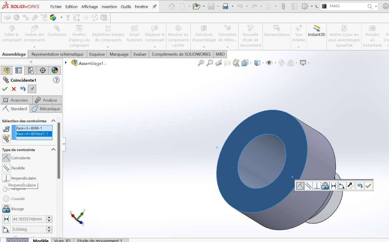
Adding the Second Link
- Insert the second biellette underneath the first one, with the rod end in between
- Use Coaxial and Coincident constraints for alignment
- Add a Coincident constraint between the two link faces for perfect overlap
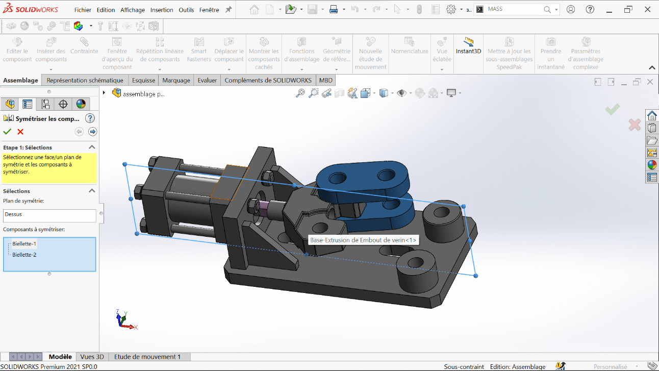
Creating Symmetry
- Use the Top Plane and the Symmetric Components tool to mirror and complete all four links required for the gripper
Adding the Jaw Holders
- Insert the Jaw Holder using Coaxial and Coincident constraints
- Apply symmetry with respect to the Top Plane, as done previously
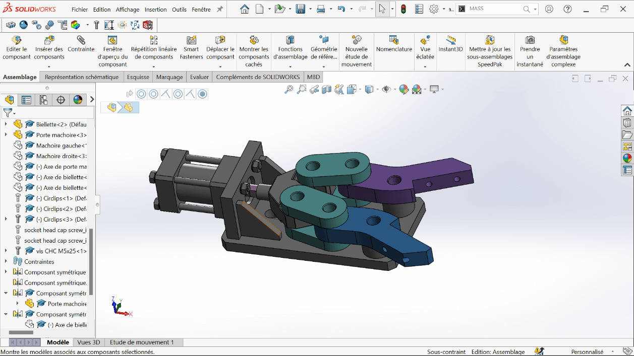
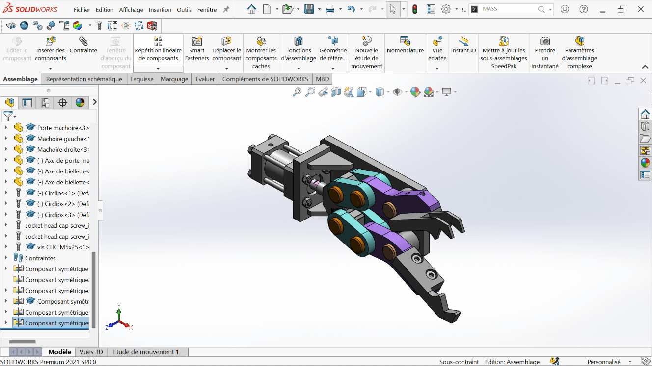
Finalizing Assembly
- Insert the jaws (left and right)
- Add all fasteners and fixings:
- M5×16 screws
- M5×25 screws
- Link and jaw axles
- Circlips for locking
- This results in the complete mechanical gripper
Complementary Tasks
--> 1. Center of Gravity – Open Position
- Fix the rod end at the minimum extension
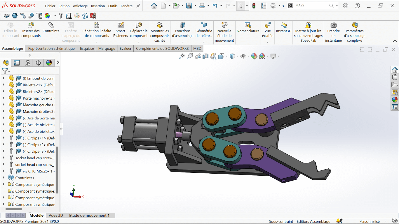
- Analyze the center of gravity of the entire assembly in this fully open position
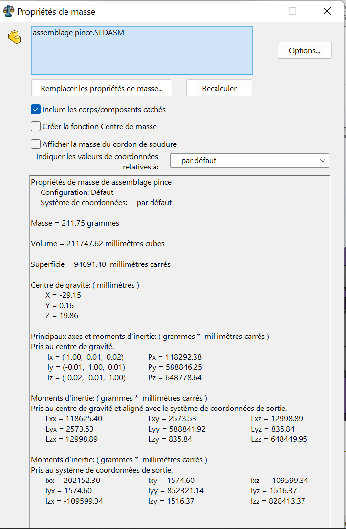
| Configuration | X (mm) | Y (mm) | Z (mm) |
|---|---|---|---|
| Fully Open | -29.15 | 0.16 | 19.86 |
--> 2. Center of Gravity – Closed Position
- Fix the rod end at the maximum extension
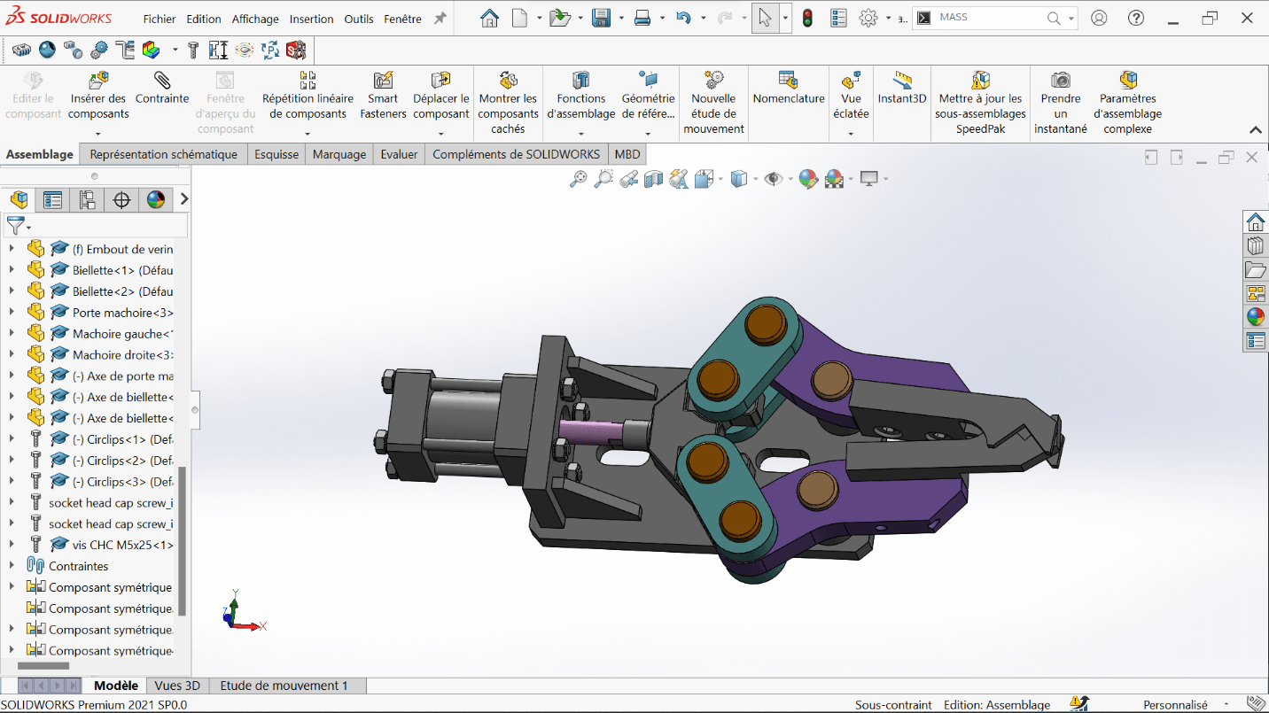
- Analyze the center of gravity in this fully closed configuration
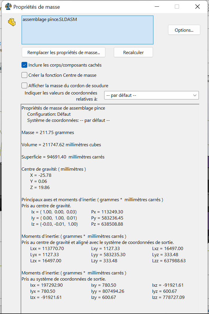
| Configuration | X (mm) | Y (mm) | Z (mm) |
|---|---|---|---|
| Fully Closed | -25.78 | 0.06 | 19.86 |
Errors Encountered
Problem
During the installation of SolidWorks, I encountered an issue that initially prevented successful setup.
Solution
The problem was resolved after watching a step-by-step tutorial video that clearly demonstrated the correct installation procedure and highlighted settings we had previously overlooked.
Perspectives
-
Part Optimization: Future versions of the mechanical components could explore new materials or lightweight geometries to reduce mass and improve energy efficiency.
-
Smarter Gripping Mechanisms: Integration of force sensors, soft grippers, or motor feedback could make the gripper more adaptive to different object shapes and textures.
-
System Integration: The validated modules can be scaled into more complex robotic systems, such as mobile manipulators or industrial automation platforms.
-
Simulation Before Prototyping: Leveraging SolidWorks Motion Studies, MATLAB/Simulink, or ROS-based environments for dynamic testing and control strategy validation before fabrication.
Resources
Installation Guides
-
Official SolidWorks Installation Guide (EN)
Detailed instructions to install SolidWorks on a single computer. -
SolidWorks Admin & Deployment Guides
For advanced installations, network licenses, and administrative deployments. -
SolidWorks Downloads Portal
Access to installation files, service packs, and updates (login required).
Official Tutorials & Manuals
-
Student’s Guide to Learning SolidWorks (PDF)
A comprehensive beginner workbook with hands-on exercises. -
MySolidWorks – Online Training Hub
Interactive tutorials, certification prep, and beginner-to-advanced courses.
Beginner-Friendly Video Tutorials
-
SolidWorks Tutorial for Beginners #1 – CAD CAM Tutorials (YouTube)
Start modeling with sketches, constraints, and extrusion. -
SolidWorks 2020 Full Beginner Tutorial – Aryan Fallahi (YouTube)
A concise intro to interface, part design, and assemblies. -
SolidWorks Tutorials for Beginners (Website)
Detailed walkthroughs on tools, menus, and modeling strategies.
Additional Resources
-
Last Minute Engineers – CAD & Arduino Projects
Perfect for blending SolidWorks with real-world embedded projects. -
GrabCAD Library – SolidWorks Files
Thousands of free SolidWorks models and parts to download and explore. -
SolidWorks Forums (EN)
Ask questions, get help, and join discussions with the global community.