Electronic
System Overview
The smart conveyor system integrates several electronic components to ensure automated waste sorting by color. The system operates in several sequential stages to detect, identify, and sort waste autonomously.
Operating Principle
The conveyor remains stationary until waste is detected. Once detected, the system activates the motor to move the waste to the sorting zone, identifies its color, transmits data to the server, and indicates the appropriate bin via LEDs.
Download files
Kicad file
Arduino files
Electrical schematic
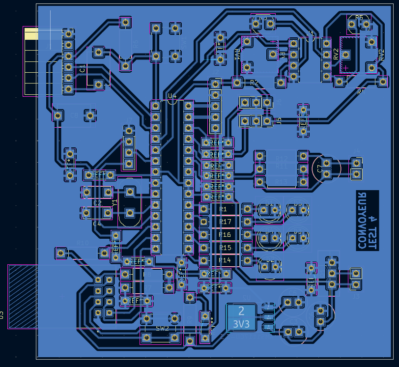
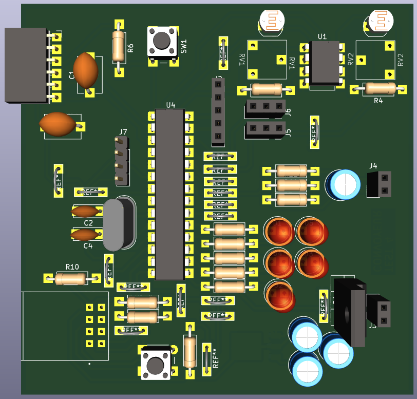
The electrical schematic presented below constitutes the complete synthesis of the system's electronic architecture. It integrates all components, circuits, and interconnections necessary for optimal installation operation.
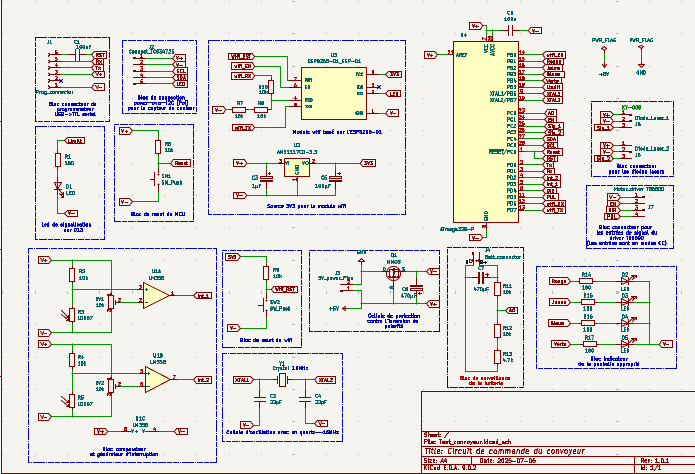
The schematic is organized into several functional sub-blocks, each playing a crucial role in the overall operation :
DEEEK Robot Programmer Block
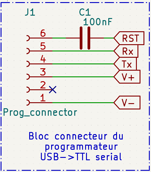
This block shows the connection interface for the DEEEK Robot USB-to-TTL programmer. The 6-pin connector (J1) provides standard programming signals: power supply (V+/V-), serial communication (Tx/Rx), and reset control (RST). The 100nF capacitor (C1) on the reset line filters noise and ensures reliable reset signal during programming operations.
Color Sensor Connection Block
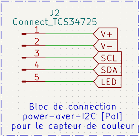
This block provides the power-over-I2C connection interface for the TCS34725 color sensor. The 5-pin connector (J2) supplies power (V+/V-), I2C communication lines (SCL/SDA), and LED control signal. This configuration allows the color sensor to operate with integrated illumination control for accurate color detection.
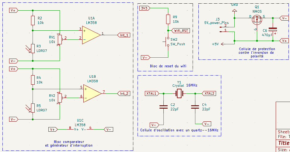
Comparator and Interrupt Generator Block
This block contains two LM358 op-amp comparators (U1A, U1B) with adjustable thresholds using LDR07 potentiometers and 10k pull-up resistors. The comparators generate digital interrupt signals (Int_1, Int_2) from analog inputs, enabling precise threshold detection for sensor interfacing.
WiFi Reset Block
Simple reset circuit for WiFi module featuring a pull-up resistor (R9, 10k) and push-button switch (SW2). This provides manual reset capability with proper signal conditioning for reliable WiFi module restart operations.
Polarity Protection Cell
Protection circuit using a P-channel NMOS transistor (Q1) with gate control through a 470µF capacitor (C6). This cell prevents reverse polarity damage by blocking current flow when power supply polarity is incorrect, ensuring system safety.
16MHz Crystal Oscillation Cell
External clock generation circuit using a 16MHz crystal (Y1) with two 22pF load capacitors (C2, C4). This provides stable timing reference for microcontroller operations, ensuring precise timing for communication protocols and system timing.
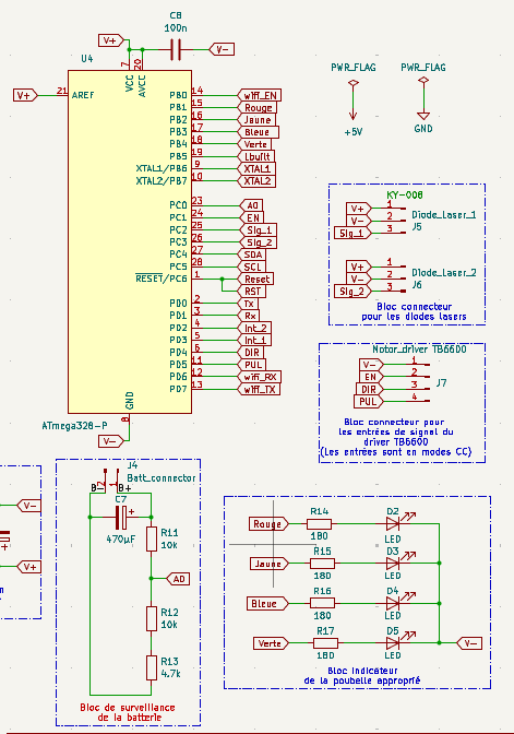
ATmega328-P Microcontroller Block
Central processing unit featuring the ATmega328-P microcontroller with external 16MHz crystal oscillation and decoupling capacitor (CB, 100n). All GPIO pins are mapped and labeled for various functions including PWM outputs, digital I/O, analog inputs, SPI, I2C, and UART communication interfaces.
PWR_FLAG Power Reference Block
Power reference symbols (+5V, GND) used for schematic clarity and proper electrical rule checking. These flags indicate power supply connection points throughout the circuit without cluttering the schematic with multiple power lines.
Diode Laser Connection Blocks
Two identical 3-pin connector blocks for diode laser modules. Each connector provides power (V+/V-) and control signal, enabling independent control of laser diodes for positioning or detection applications.
Motor Driver TB6600 Connection Block
Interface connector for TB6600 stepper motor driver module. The connector provides step/direction control signals (STP, DIR), enable control (ENA), and power connections for stepper motor control applications.
Battery Monitoring Block
Voltage monitoring circuit using precision resistors (R12, R13, R14: 4.7k each) to create voltage dividers for battery level sensing. This enables the microcontroller to monitor battery voltage through analog inputs for power management.
LED Indicator Block
Status indication circuit with multiple LEDs (Rouge, Jaune, Bleue, Verte) connected through current-limiting resistors (R15-R18: 180Ω each). These LEDs provide visual feedback for system status, operation modes, or diagnostic information.
Power Supply
Power Supply Block (4S2P Lithium Configuration)
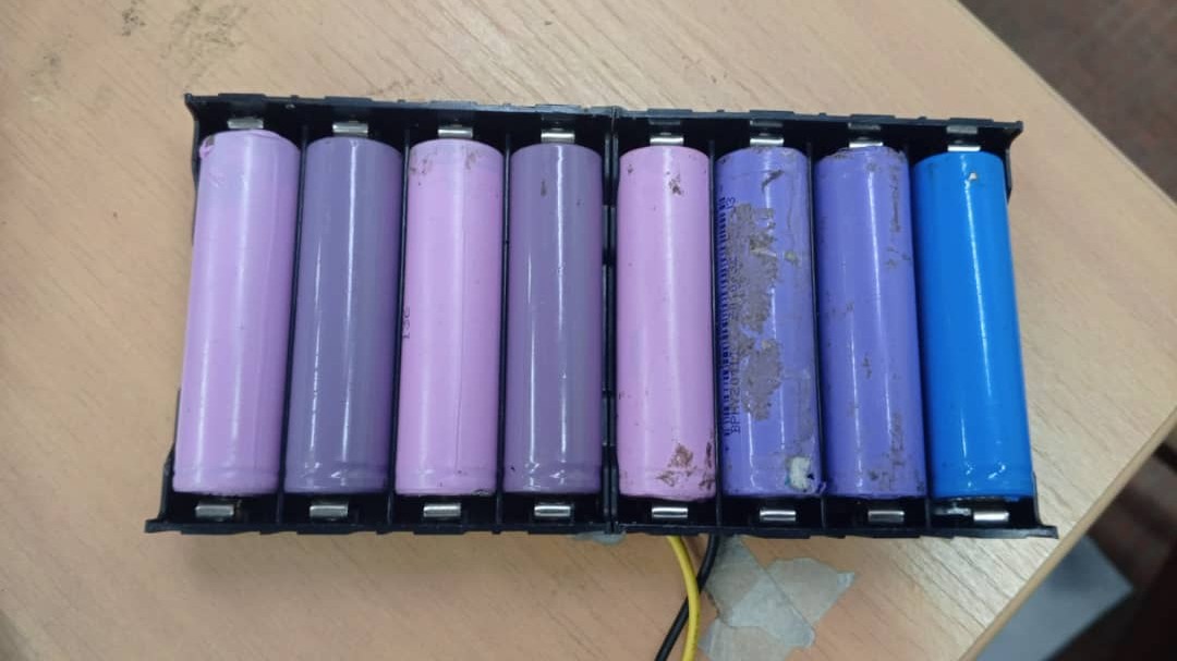
Main power system using 8 lithium cells (3.7V each) arranged in 4S2P configuration. Four cells in series provide 14.8V nominal voltage, while parallel connection doubles capacity. This configuration delivers high voltage and extended runtime for demanding applications requiring sustained power output.
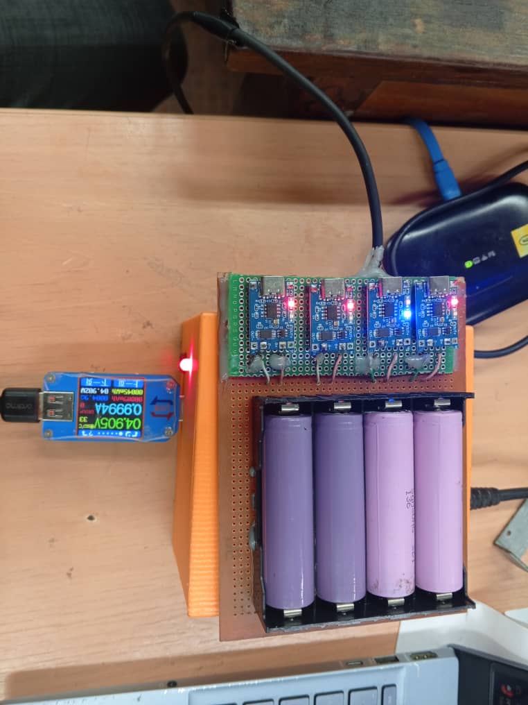
Battery Charging System
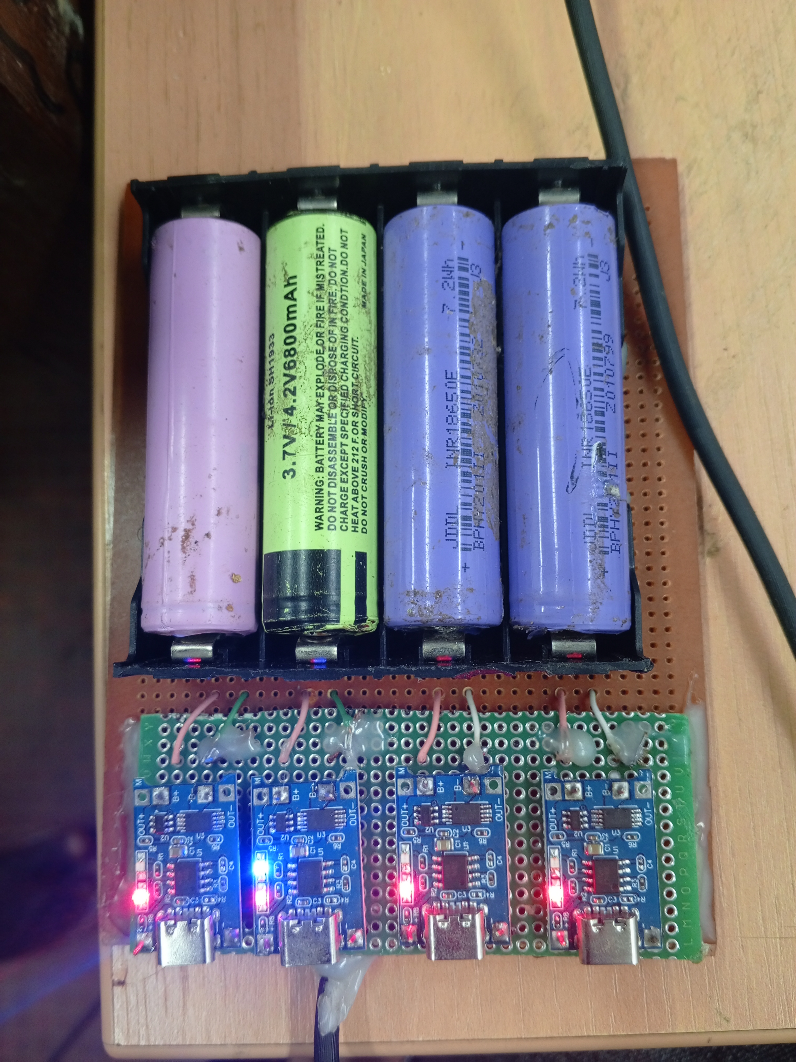
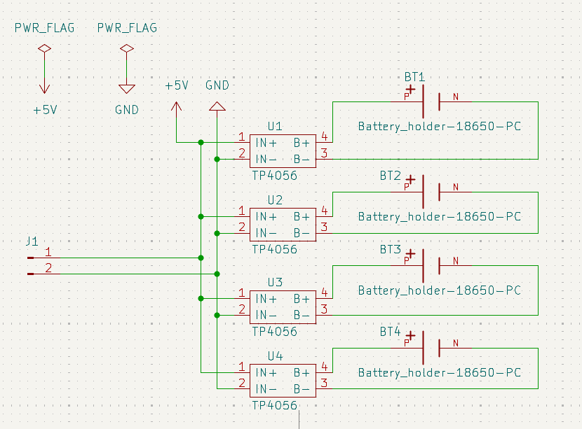
Custom charging circuit using lithium battery charging modules (TP40560) to simultaneously charge 4 cells. The system incorporates proper cell balancing and charging management to ensure safe and efficient charging of the lithium battery pack while maintaining cell longevity and preventing overcharge conditions.
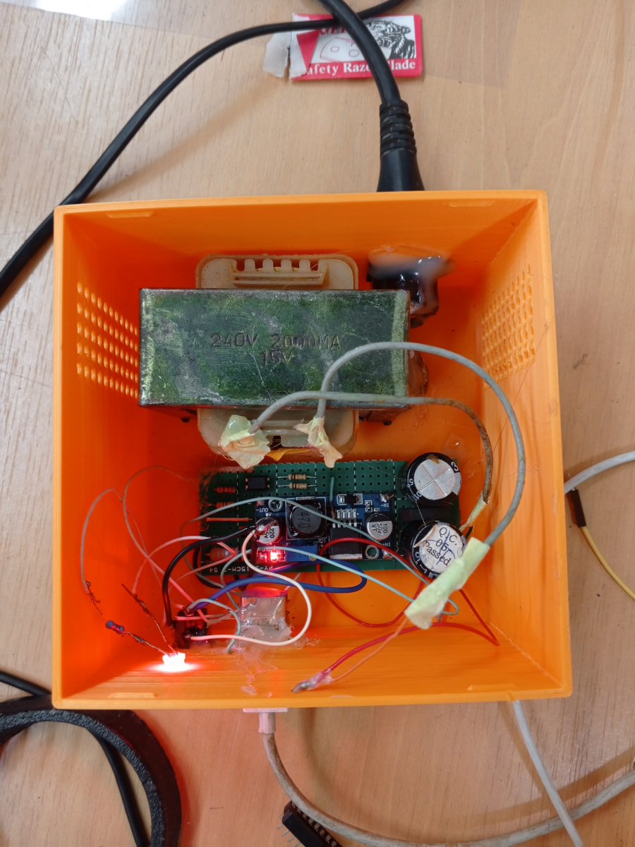
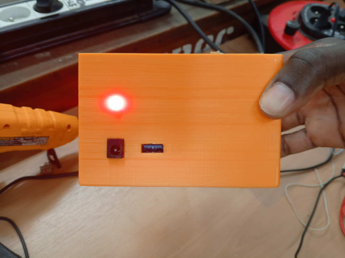
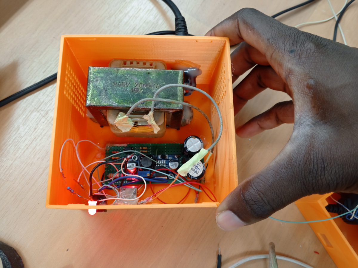
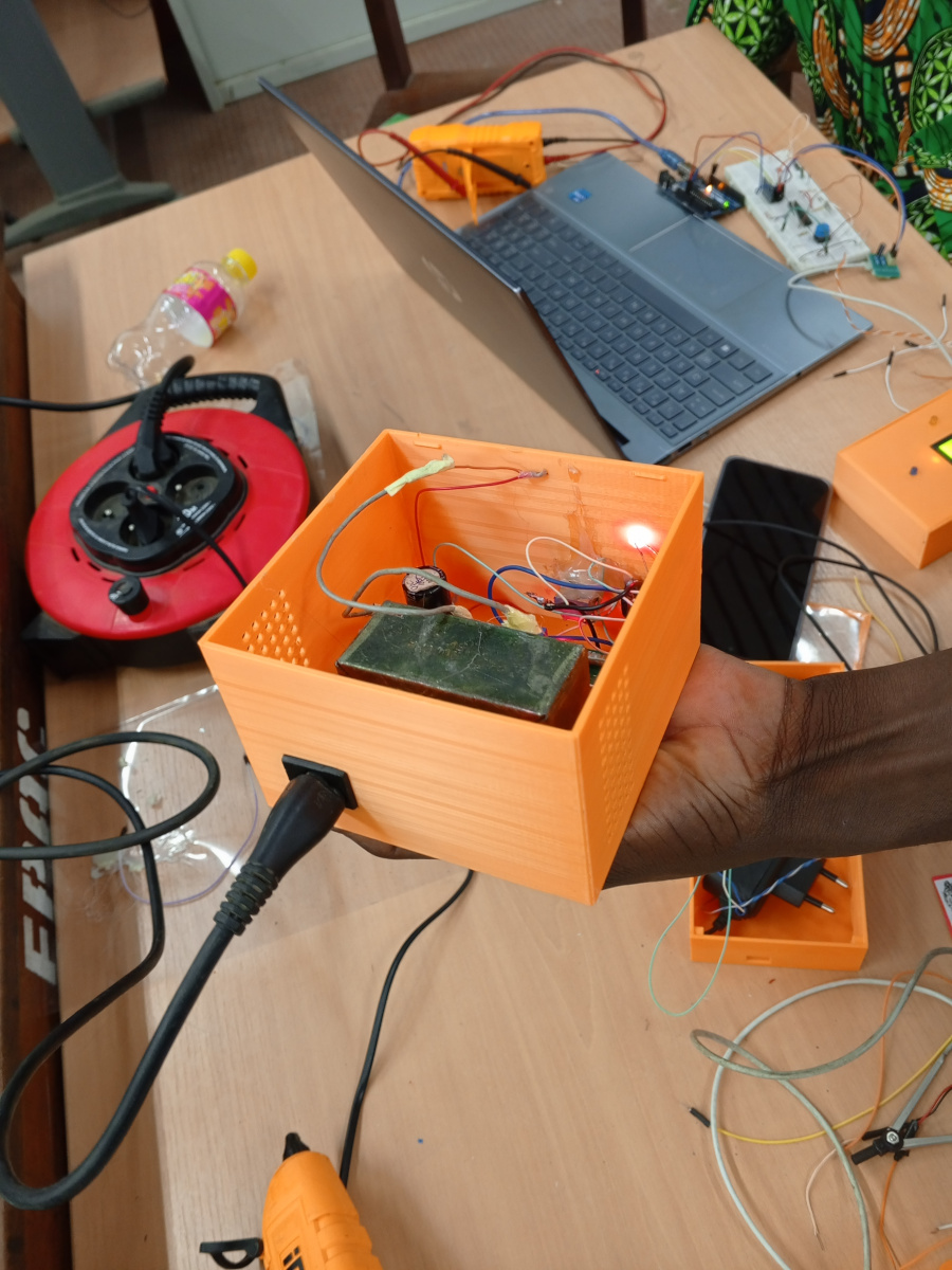
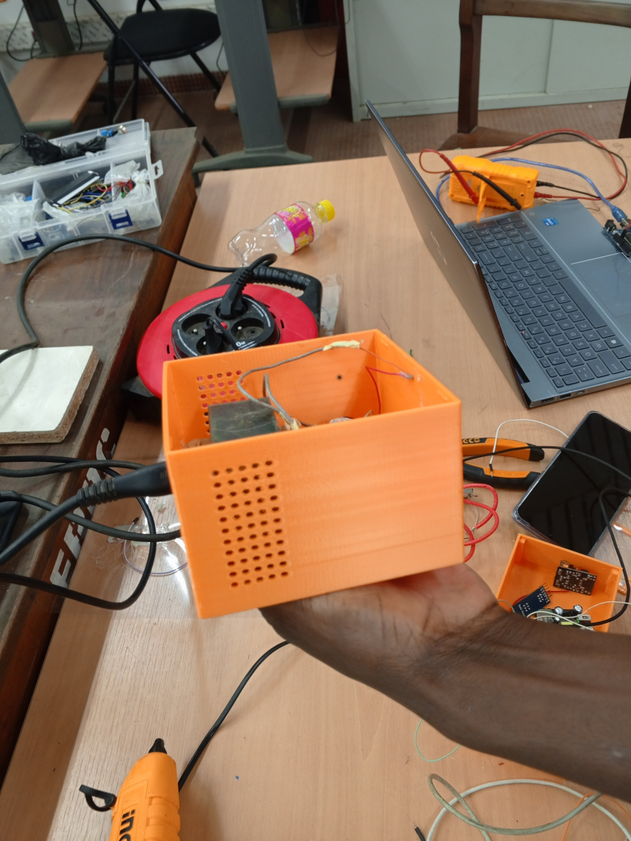
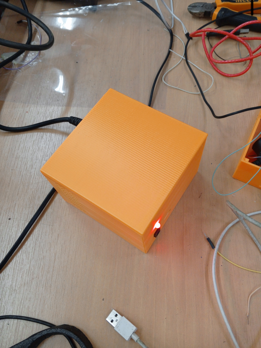
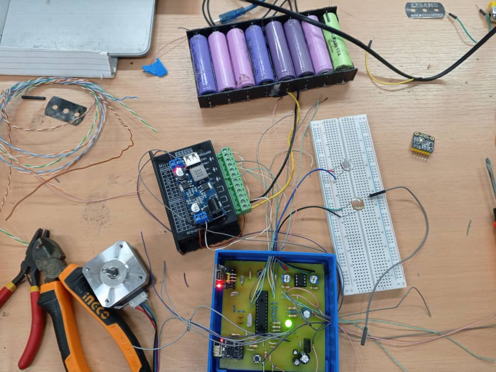
Charging Power Supply
In this test, we used the power supply built during the first test to charge batteries through the charger.
Here are the Pictures showing it :
 |  |  |
|---|---|---|
 |  |  |
Circuitry (PCB Development)
PCB Design Process
 |  |
|---|
The PCB development follows a chemical etching process for board manufacturing. Starting from the finalized schematic, the circuit layout is transferred to a copper-clad substrate using photolithographic techniques and chemical solution etching to remove unwanted copper areas, creating the desired circuit traces and pads. Manufacturing Steps
Design Transfer: Circuit pattern transferred to photoresist-coated copper board
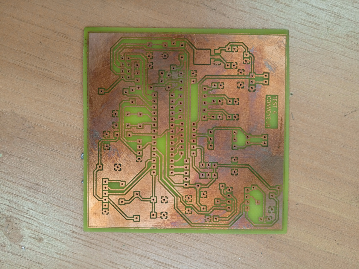
Chemical Etching: Ferric chloride or similar etching solution removes exposed copper Cleaning and Inspection: Removal of photoresist and verification of trace integrity Drilling: Precise hole drilling for component mounting and via connections
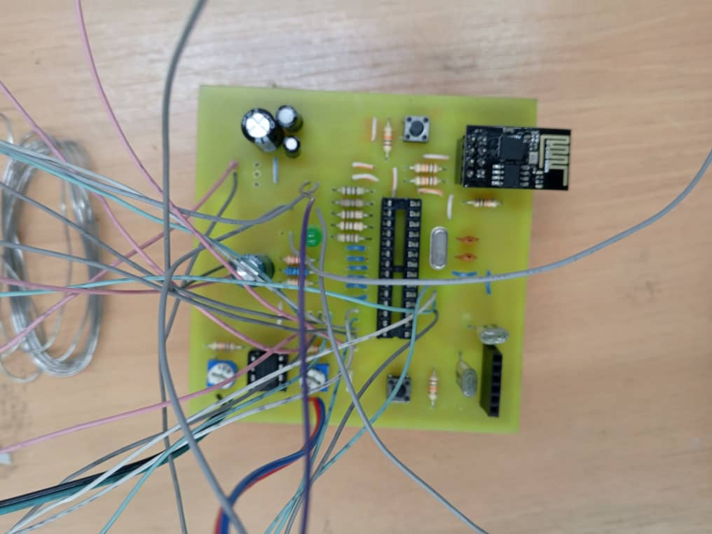
Assembly and Soldering
 |  |
|---|
Following PCB fabrication, components are mounted and soldered according to the placement plan. Soldering process includes proper flux application, temperature control, and joint inspection to ensure reliable electrical connections and mechanical stability.
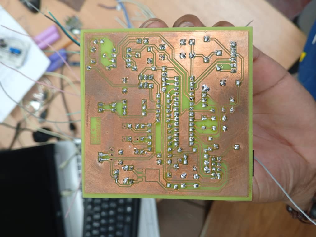
Testing and Validation
 |  |
|---|---|
 |  |
Comprehensive testing phase includes continuity checks, power supply verification, and functional testing of each circuit block. This ensures proper PCB manufacturing quality and validates that the physical implementation matches the original schematic design specifications.
Components
NEMA17 Stepper Motor
Description
The NEMA17 stepper motor is a bipolar stepper motor with 200 steps per revolution (1.8° per step). It provides precise positioning control and high torque output, making it ideal for conveyor belt systems and precise positioning applications.
Specifications
- Step Angle: 1.8° (200 steps/revolution)
- Voltage: 12V DC
- Current: 1.2A per phase
- Holding Torque: 40 Ncm
- Connection: 4-wire bipolar configuration
Wiring
The motor connects to the TB6600 driver through a 4-wire cable:
- A+/A-: Phase A coil connections
- B+/B-: Phase B coil connections
- Proper phase identification is crucial for correct rotation direction
Operation
Controlled via step and direction signals from the microcontroller through the TB6600 driver. Each pulse on the step pin advances the motor by one step, while the direction pin determines rotation direction.
[Insert NEMA17 motor image here]
KY-008 Laser Diode Module
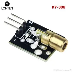
Description
The KY-008 is a 5mW red laser diode module operating at 650nm wavelength. It provides a focused laser beam for precise positioning, detection, or alignment applications in the conveyor system.
Specifications
- Wavelength: 650nm (red)
- Power Output: 5mW
- Operating Voltage: 5V DC
- Current Consumption: sup 40mA
- Beam Diameter: sup1.5mm at 3m distance
Wiring
Simple 3-pin connection:
- VCC: +5V power supply
- GND: Ground reference
- S: Signal/control pin (can be PWM controlled)
Operation
The laser can be controlled digitally (ON/OFF) or with PWM for intensity modulation. Connect the signal pin to a microcontroller GPIO for precise timing control during object detection or positioning tasks.
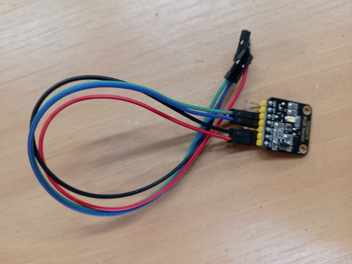
TCS34725 Color Sensor
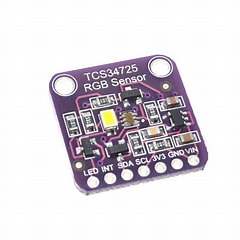
Description
The TCS34725 is a digital color sensor with RGB and clear light sensing capability. It features an integrated IR blocking filter and provides accurate color detection through I2C communication interface.
Specifications
- Communication: I2C interface
- Supply Voltage: 3.3V or 5V
- Detection Range: High sensitivity with programmable gain
- Color Filters: Red, Green, Blue, and Clear (RGBC)
- I2C Address: 0x29
Wiring
Standard I2C connection with 5 pins:
- VCC: Power supply (3.3V or 5V)
- GND: Ground reference
- SDA: I2C data line
- SCL: I2C clock line
- LED: Integrated LED control (optional)
Operation
Communicates via I2C protocol to provide RGBC values. The sensor can automatically adjust integration time and gain for optimal color detection. Integrated LED provides consistent illumination for accurate color readings.
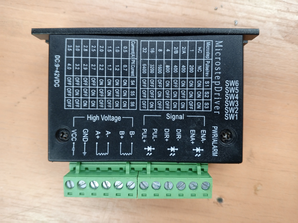
TB6600 Stepper Motor Driver
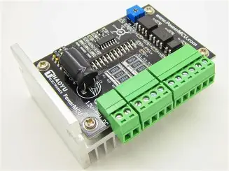
Description
The TB6600 is a professional stepper motor driver capable of driving 4A, 40V stepper motors. It features microstepping capability, over-current protection, and simple step/direction interface.
Specifications
- Input Voltage: 12-40V DC
- Output Current: 0.5-4A (adjustable)
- Microstepping: 1, 2, 4, 8, 16, 32 subdivision
- Control Interface: Step/Direction/Enable
- Protection: Over-current, over-temperature
Wiring
Power Connections:
- VCC/GND: 12-40V power input
- A+, A-, B+, B-: Motor phase connections
Control Connections:
- PUL+/PUL-: Step pulse input
- DIR+/DIR-: Direction control input
- ENA+/ENA-: Enable control input
Operation
The driver receives step pulses and direction signals from the microcontroller. Internal DIP switches configure current setting and microstepping resolution. Each pulse on PUL input advances the motor by one microstep.
Photoresistor (LDR)
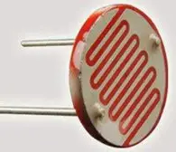
Description
Light Dependent Resistor (LDR) is a passive component whose resistance varies inversely with incident light intensity. Used for ambient light detection and automatic brightness control applications.
Specifications
- Dark Resistance: 1MΩ (typical)
- Light Resistance: 10-20kΩ (at 10 lux)
- Response Time: 20-30ms (light to dark)
- Operating Temperature: -30°C to +70°C
- Peak Wavelength: 540nm (green light)
Wiring
Simple voltage divider configuration:
- One terminal: Connect to VCC through pull-up resistor (10kΩ)
- Other terminal: Connect to GND
- Output: Voltage divider junction to ADC input
Operation
Forms a voltage divider with a fixed resistor. As light intensity increases, LDR resistance decreases, causing output voltage to change. This analog voltage is read by the microcontroller's ADC for light level measurement and threshold detection.
[Insert photoresistor/LDR image here]
Integration Notes
All components integrate through the main microcontroller (ATmega328-P) which coordinates their operation:
- Stepper motor: Controlled via TB6600 driver for precise positioning
- Laser diode: Provides optical reference for object detection
- Color sensor: Identifies object colors via I2C communication
- Photoresistor: Monitors ambient conditions and triggers based on light levels
This configuration enables a complete automated sorting and positioning system with optical feedback and precise mechanical control.
Arduino Code
Pin Configuration Table
| Pin | Function | Type | Description |
|---|---|---|---|
| 2 | Interrupt Input | Digital Input | Start beam sensor (departure detection) |
| 3 | Interrupt Input | Digital Input | End beam sensor (finish detection) |
| 4 | MOTOR_DIR | Digital Output | Stepper motor direction control |
| 5 | MOTOR_PULSE | Digital Output | Stepper motor pulse/step control |
| 6 | ESP01 TX | Software Serial | Communication with ESP8266 (TX) |
| 7 | ESP01 RX | Software Serial | Communication with ESP8266 (RX) |
| 8 | Power Control | Digital Output | Power control output (set HIGH) |
| 13 | LED Indicator | Digital Output | Motor status LED indicator |
| 15 | MOTOR_ENABLE | Digital Output | Stepper motor enable control |
| A0 | Battery Monitor | Analog Input | Battery voltage monitoring |
Code Structure Analysis
Library Includes and Definitions Block
#include <Arduino.h>
#include <SoftwareSerial.h>
#define MOTOR_DIR 4
#define MOTOR_PULSE 5
#define MOTOR_ENABLE 15
Purpose: Sets up required libraries and defines motor control pins for clear code readability and easy pin reassignment.
Global Variables Block
long step_time = 500;
SoftwareSerial esp01(7, 6);
volatile int count_depart = 0;
bool tapis_en_marche = false;
Purpose: Declares system-wide variables including motor timing, ESP8266 communication object, counters, and system state flags.
Interrupt Service Routines Block
void departTapis() { /* start detection */ }
void finTapis() { /* end detection */ }
Purpose: Handle real-time object detection events. These functions execute immediately when beam sensors detect objects entering or leaving the conveyor.
Sensor Functions Block
void senseWasteColor() { /* color detection */ }
void senseBatteryCharge() { /* battery monitoring */ }
Purpose: Encapsulate sensor data collection. Color sensing is currently simulated, while battery monitoring reads actual analog values with calibration.
System Initialization Block (setup)
void setup() {
  Serial.begin(9600);
  pinMode configurations;
  attachInterrupt setup;
}
Purpose: Configures all hardware interfaces, communication protocols, and interrupt handlers. Establishes initial system state before main operation begins.
Main Control Loop Block
void loop() {
  if(tapis_en_marche) {
    // Motor control sequence
    // Data collection
    // Communication handling
  }
}
Purpose: Implements the main operational cycle. Manages motor control, coordinates sensor readings, and handles ESP8266 communication based on system state.
Main Functions
Setup Function
void setup()
Purpose: Initializes system components and configuration
- Configures serial communication (9600 baud)
- Sets up GPIO pin modes and initial states
- Initializes ESP8266 communication
- Attaches interrupt handlers for beam sensors
- Configures stepper motor control pins
Main Loop
void loop()
Purpose: Main program execution cycle
- Monitors conveyor belt status
- Controls stepper motor operation when objects are detected
- Handles sensor data collection and WiFi transmission
- Manages system timing and delays
Interrupt Handlers
departTapis()
void departTapis()
Purpose: Triggered when object enters conveyor (pin 2 rising edge)
- Sets conveyor running flag to true
- Activates status LED
- Prints detection message to serial
finTapis()
void finTapis()
Purpose: Triggered when object exits conveyor (pin 3 rising edge)
- Sets conveyor running flag to false
- Deactivates status LED
- Prints detection message to serial
Sensor Functions
senseWasteColor()
void senseWasteColor()
Purpose: Color detection simulation
- Currently simulates green color detection
- In production, would interface with TCS34725 color sensor
senseBatteryCharge()
void senseBatteryCharge()
Purpose: Battery voltage monitoring
- Reads analog voltage from pin A0
- Averages 5 readings for stability
- Applies calibration ratio (4.167) and scaling
- Calculates percentage charge relative to 16.8V maximum
System Operation Flow
- Initialization: System starts with motor disabled and sensors armed
- Object Detection: Beam break on pin 2 triggers conveyor start
- Motor Control: Stepper motor runs with 500μs step timing
- Object Exit: Beam break on pin 3 stops conveyor
- Data Collection: Color sensing and battery monitoring execute
- Communication: Data transmitted to ESP8266 in format "color#battery"
- Response Handling: System waits for ESP8266 acknowledgment
Communication Protocol
Data Format
"color#battery_percentage"
Example: "green#95"
Communication Sequence
- Arduino sends data string to ESP8266
- Arduino waits for ESP8266 response
- ESP8266 response is displayed on serial monitor
- Communication buffers are flushed
Configuration Parameters
| Parameter | Value | Description |
|---|---|---|
| step_time | 500μs | Stepper motor step pulse width |
| ratio | 4.167 | Battery voltage calibration factor |
| Serial Baud | 9600 | Communication speed |
| Max Battery | 16.8V | Maximum battery voltage reference |
Safety Features
- Motor Enable Control: Motor is disabled when not in use
- Interrupt-Based Detection: Reliable object detection using hardware interrupts
- Battery Monitoring: Continuous power level surveillance
- Communication Timeout: Prevents system lockup during WiFi issues
Development Notes
- Code includes commented legacy communication functions for reference
- Battery monitoring uses averaged readings for improved accuracy
- System designed for expandability with additional sensors
- Modular function structure allows easy modification and testing
This implementation provides a robust foundation for automated sorting applications with real-time monitoring and wireless connectivity capabilities.
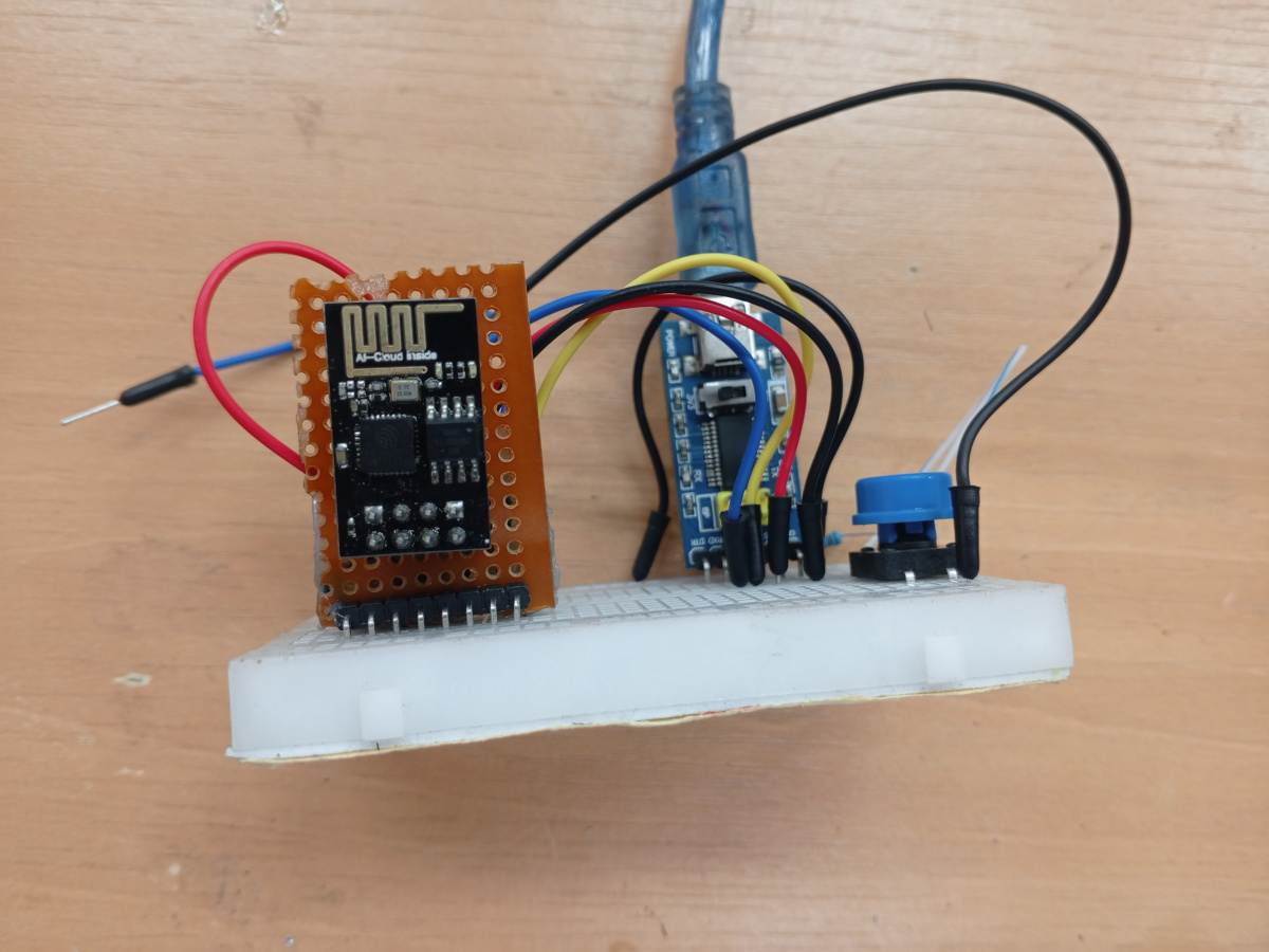
ESP8266 Code
Configuration Parameters Table
| Parameter | Value | Description |
|---|---|---|
| Serial Baud | 9600 | Communication speed with Arduino |
| WiFi SSID | "Moov -Africa" | Target wireless network name |
| WiFi Password | "@@password@" | Network authentication password |
| Flask Server Host | "192.168.1.100" | Backend server IP address |
| Flask Server Port | 5000 | HTTP communication port |
| Connection Retries | 50 | Maximum WiFi connection attempts |
| Retry Delay | 500ms | Delay between connection attempts |
Code Structure Analysis
Library Includes and Configuration Block
#include <Arduino.h>
#include <ESP8266WiFi.h>
#include <ESP8266HTTPClient.h>
const char* ssid = "Moov -Africa";
const char* flaskServerHost = "192.168.1.100";
Purpose: Imports essential libraries for WiFi connectivity and HTTP communication. Defines network credentials and server configuration for the sorting system's backend communication.
Global Variables Block
String color, batteryLevel, data;
String apiEndpoint = "";
unsigned long previousMillis = 0;
const long interval = 2000;
Purpose: Declares variables for data parsing, API endpoint construction, and timing control. These variables manage the communication flow between Arduino sensor data and Flask server.
WiFi Initialization Block (setup)
void setup() {
  Serial.begin(9600);
  WiFi.begin(ssid, password);
  while (WiFi.status() != WL_CONNECTED && retries < 50) {
    // Connection attempt loop
  }
}
Purpose: Establishes serial communication with Arduino and attempts WiFi connection with retry mechanism. Provides connection status feedback and handles connection failures gracefully.
Data Reception Block
if (Serial.available()) {
  data = Serial.readStringUntil('\n');
  Serial.println("D");
}
Purpose: Monitors serial input from Arduino and receives sensor data in "color#battery" format. Sends acknowledgment ("D") back to Arduino confirming data reception.
Data Parsing Block
int sep = data.indexOf('#');
if (sep > 0) {
  color = data.substring(0, sep);
  batteryLevel = data.substring(sep + 1);
}
Purpose: Extracts color and battery information from received string using delimiter parsing. Separates the combined data into individual parameters for API transmission.
HTTP Request Construction Block
apiEndpoint = "/api/set?color=" + color + "&battery=" + String(batteryLevel);
String serverPath = "http://" + String(flaskServerHost) + ":" + String(flaskServerPort) + String(apiEndpoint);
Purpose: Builds complete HTTP GET request URL with query parameters. Combines server configuration with parsed sensor data to create valid API endpoint.
HTTP Communication Block
WiFiClient client;
HTTPClient http;
if (http.begin(client, serverPath)) {
  int httpCode = http.GET();
  if (httpCode > 0) {
    // Handle response
  }
}
Purpose: Executes HTTP GET request to Flask server and handles response codes. Manages connection lifecycle and provides error handling for network communication.
System Operation Flow
- Initialization: ESP8266 starts and attempts WiFi connection with retry mechanism
- Connection Status: Reports success ("Connected") or failure ("X not Connected")
- Data Monitoring: Continuously monitors serial input from Arduino
- Data Reception: Receives "color#battery" format data and acknowledges with "D"
- Data Parsing: Splits received string into color and battery components
- API Construction: Builds HTTP GET request with parsed parameters
- HTTP Transmission: Sends data to Flask server and handles response
- Status Reporting: Returns HTTP response code to serial monitor
Communication Protocol
Arduino to ESP8266
- Format:
"color#battery_level\n" - Example:
"green#95\n" - Acknowledgment: ESP8266 responds with
"D"
ESP8266 to Flask Server
- Method: HTTP GET
- Format:
/api/set?color=VALUE&battery=VALUE - Example:
http://192.168.1.100:5000/api/set?color=green&battery=95
Error Handling Features
- WiFi Connection: Maximum 50 retry attempts with 500ms delays
- HTTP Response: Checks for valid response codes (200, 301)
- Data Validation: Verifies delimiter presence before parsing
- Connection Management: Proper HTTP client cleanup after requests
Network Configuration
The system supports multiple WiFi networks (commented alternatives available):
- Primary: "Moov -Africa" network
- Alternative: "marzou" network (commented)
- Server communication via local IP address (192.168.1.100)
This implementation provides robust wireless communication between the sorting system and backend server with comprehensive error handling and status monitoring.