Mechanic
1. Introduction
The mechanical component is the fundamental pillar of the waste sorting conveyor system. It must guarantee the robustness, precision, and ergonomics required to ensure reliable operation in accordance with specifications. This report details every aspect of the project's design, modeling, and mechanical implementation.
2. Mechanical Specifications
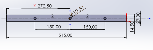
- Total length of the conveyor: 650 mm (imposed to adapt to the industrial space and guarantee sufficient sorting capacity).
- Height of the carpet from the floor: 100 mm (optimized for manual collection and accessibility).
- Objects to sort: Cubes of 30 mm on each side, simulating different types of waste.
- Stability and robustness: Structure designed to support the weight of objects and components, while resisting vibrations.
- Accessibility: Clear conveyor exit to facilitate manual collection.
- Sensor integration: Specific supports for precisely positioning presence and color sensors.
3. Design and Modeling
3.1 Software Used
SolidWorks: Used for 3D modeling, creating technical drawings and assembly simulation. This choice allows you to anticipate interference problems, optimize ergonomics and generate files for manufacturing (3D printing, CNC cutting, etc.).
3.2 Conveyor Structure
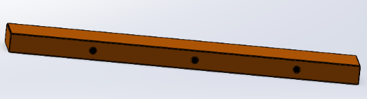
- Main chassis:
- Made of wood or PLA (type 650 x 16.28 x 200 mm) to combine lightness, rigidity and modularity.
- T-slot assembly
- Treadmill:
- Reinforced rubber or leather band, selected for its grip and availability.
- Width suitable for the passage of 80 mm cubes with a safety margin to avoid blockages.
- Tensioning system by a plate located between the two drums
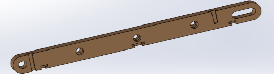
- Side supports:
- Wooden plates fixed on either side of the mat to guide objects and prevent them from falling.
- Height adjusted to allow the cubes to pass through without excessive friction.
- Feet:
- Wooden legs.
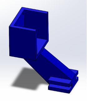
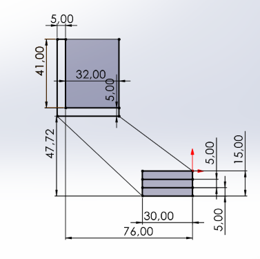
3.3 Sensor Integration
- Presence sensor support:
- Positioned at the entrance of the conveyor, just above or to the side of the belt.
- Made using 3D printing for precise adjustment to the sensor geometry (KY-008 laser or photoresistor).
- Color sensor support:
- Placed in a central detection zone, just above the mat.
- Rigid mounting to avoid vibrations that could distort the reading.
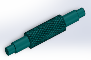
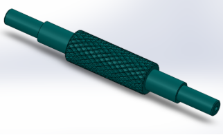
3.4 Transmission
- Transmission system:
- The transmission is ensured by pressure screw on the flat of the engine output shaft
- Carpet tension:
- Adjustment by lateral displacement of the bearing assembly, return drum by helical connection.
3.5 Choice of materials
For the design of the parts, we initially planned to use PLA via 3D printing. However, due to financial constraints, we started manufacturing with teak wood, a more economical and readily available material. Thus, the majority of the parts produced so far are made of wood.
We were recently informed that 3D printing could be done on a voluntary basis, thanks to an agreement with our mentor and the SCOP. This opportunity will allow us to consider manufacturing certain parts in PLA, which offers greater precision and durability.
3.6 Selection of bearings
Conveyor drums must primarily support radial loads, resulting from the weight of the conveyor belt and the waste to be conveyed. Therefore, it is essential to choose bearings suitable for this type of load.
After analysis, we opted for single-row, radial contact ball bearings, which effectively respond to radial constraints while offering good reliability and simplified maintenance.
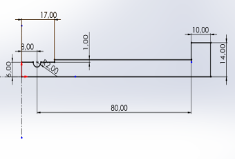
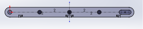
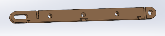
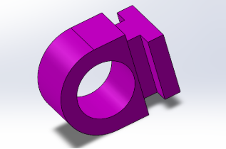
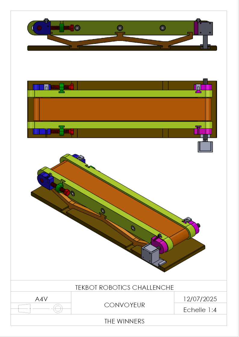
4. Plans and Diagrams
-
General plans:
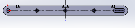
- Isometric view showing the entire conveyor and component layout.
 Base
Base
- Isometric view showing the entire conveyor and component layout.
-
Room W
-
Left Side Support
-
Right side support
-
Countershaft bearing
-
 Tensioner support
 -
Tensioner ring
-
Engine side bearing
-
M14 screw
-
Return drum
-
Control drum
-
Holding plate
-
Sensor
-
 Engine mount
4. Plans et Schémas
- Plans d’ensemble :
- Vue isométrique montrant la totalité du convoyeur et la disposition des composants.
- Vues de face, dessus
Manufacturing Process
3D Printing Process (PLA Components)
Equipment Used
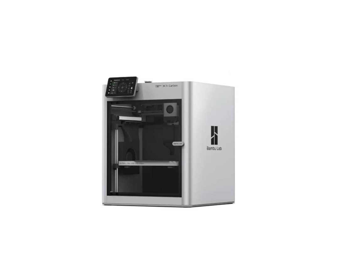
- Bambu Lab X1-Carbon: High-speed precision printing
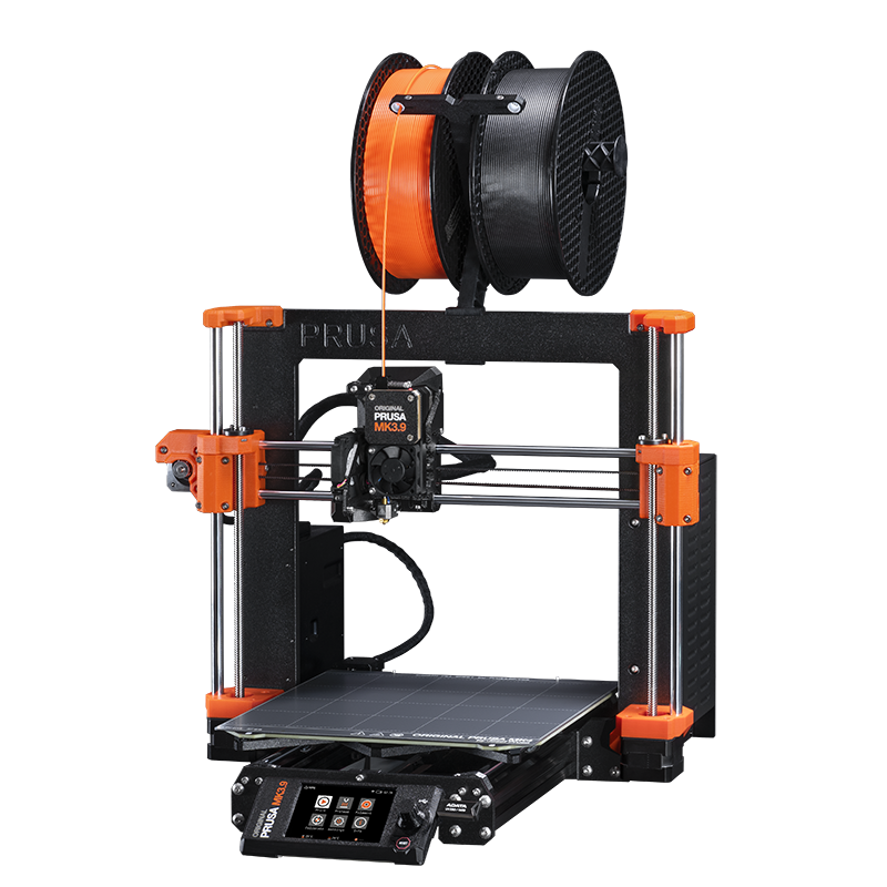
- Prusa MK4S: Reliable backup and parallel production
Manufacturing Steps
1. Design Preparation
- CAD files converted to STL format
- Print orientation optimized for strength and support requirements
- Layer height and infill parameters configured based on component function
2. Slicing Configuration
- Layer Height: 0.2mm for optimal surface finish
- Infill Density: 20-30% depending on structural requirements
- Print Speed: Optimized for PLA material properties
- Support Structures: Generated for overhanging features
3. Printing Process
- Heated bed temperature set for PLA adhesion
- Nozzle temperature calibrated for consistent extrusion
- Print monitoring for quality control
- Multi-part printing when possible to optimize build time
4. Post-Processing
- Support material removal using appropriate tools
- Surface finishing and cleanup of print artifacts
- Dimensional verification against design specifications
- Fit testing with mating components
Wood Cutting Process (Structural Components)
Equipment Used
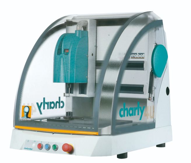
- Charly 2U CNC Mill: Precision wood cutting and shaping
Manufacturing Steps
1. Material Preparation
- Wood stock selection and quality inspection
- Material dimensioning and squaring
- Workpiece clamping and alignment on CNC table
2. CAM Programming
- CAD designs converted to G-code toolpaths
- Tool selection based on wood type and cut requirements
- Cutting parameters optimized for surface finish and tool life
- Safety clearances and rapid move paths defined
3. CNC Machining Process
- Tool installation and length compensation setup
- Workpiece origin establishment and coordinate system setup
- Automated cutting sequence execution
- Real-time monitoring for quality and safety
4. Quality Control
- Dimensional verification using precision measuring tools
- Surface finish inspection and smoothing if required
- Edge deburring and corner radius finishing
- Final fit and assembly testing
Assembly Integration
Component Verification
- All 3D printed parts checked for dimensional accuracy
- Wood components inspected for proper machining tolerances
- Hardware compatibility verified before final assembly
Assembly Process
- Systematic assembly following predetermined sequence
- Hardware installation with appropriate torque specifications
- Mechanical alignment and adjustment procedures
- Functional testing of moving parts and mechanisms
Final Inspection
- Complete system dimensional verification
- Mechanical function testing under operational conditions
- Safety feature validation and compliance checking
- Documentation of any modifications or adjustments made
This manufacturing approach combines the precision of CNC machining for structural components with the flexibility of 3D printing for custom mechanical parts, ensuring optimal performance and cost-effectiveness for the conveyor system.
Sizing a conveyor
1. Length of the strip
The total length L of the strip is given by the following relation:
L = 2a + 2πD
With: - a = 580 mm: average center distance between the two drums, - D = 30 mm: diameter of the drum.
We therefore have:
2. Engine selection
a. Calculation of engine torque
The torque required to drive the conveyor is given by the following formula:
The friction force is expressed by:
Ffriction = μ × (m + mb × L) × g
With: - : coefficient of friction between the belt and the knurled drum, - m : mass to be moved, - : density of the material (PLA), - : linear mass of the belt, - g = 9.81 m/s² : gravitational acceleration.μ = 0,5ρ=1.24 g/cm3mb = 0,0523 g/mm
We estimate the mass to be moved:
m = V × ρ = c³ × ρ = 33,5 g = 0,0335 kg
So the friction force is:
Ffriction= 0,5 × (0,0335 + (0,0523 × 1348)/1000) × 9,81
So the couple is:C
b. Engine selection
The motor to be used must therefore provide a torque greater than 0.00765 Nm. The Nema 17HS44011S motor offers a torque of 0.43 Nm, which is more than enough to drive the conveyor.
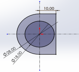
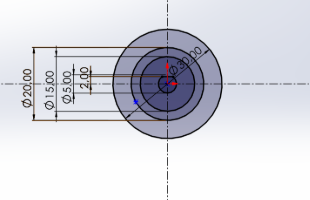
3. Choice of bearings
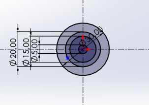
To support radial forces on the drum axles, the use of single-row ball bearings (radial contact) is proposed.
Bearing characteristics: - Inner diameter or bearing seat diameter: d = 15 mm, - Outer diameter or bore diameter: D = 28 mm. This is the technical data sheet of a single row radial contact ball bearing which meets the constraints of the inner diameter of the shaft and the outer diameter of the bore.
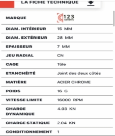
These characteristics are more than sufficient for the forces generated by our conveyor system.