2nd Test
Ojectives
Evaluate your advanced CAD skills using SolidWorks through :
- Designing parts,
- Modifying existing components,
- And creating an assembly.
Summary
Files available for download
Download the modeling files by clicking by following these links :
Part 1
-
Case 1 : SolidWorks File - Part1_case1
-
Case 2 : SolidWorks File - Part1_case2
Part 2
- Part 2 : SolidWorks File - Part2
Part 3
- Part 3 : SolidWorks File - Part3
Assembly
-
Assembly - a : SolidWorks File - Assembly_a
-
Assembly - b : SolidWorks File - Assembly_b
Design - Summary table of results
| Part | Specifications | Mass (g) |
|---|---|---|
| Part I-a | A = 81,00 ; B = 57,00 ; C = 43,00 | 939,54 |
| Part I-b | A = 84,00 ; B = 59,00 ; C = 45,00 | 1032,32 |
| Part II | A = 86,00 ; B = 58,00 ; C = 44,00 + Material removal | 628,18 |
| Part III | Pocket feature added | 432,58 |
Assembly - Summary table of results
| Center of mass coordinates (mm) | |||
|---|---|---|---|
| X | Y | Z | |
| A = 25 degrees; B = 125 degrees; C = 130 degrees | 348.66 | -88.48 | -91.40 |
| A = 30 degrees; B = 115 degrees; C = 135 degrees | 339.43 | -98.39 | -52.36 |
Video
Materials
Execution
Design and modification of parts
In this part we will have to create a part in the first part and then modify it in the other two parts.
Unit systems: MMGS (millimeter, gram, second);
Decimals: 2
All holes are through holes unless otherwise noted.
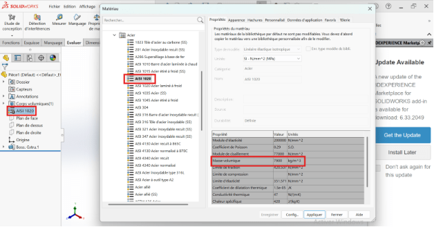
Material : AISI 1020 steel; Density: 0.0079 g/mm^3
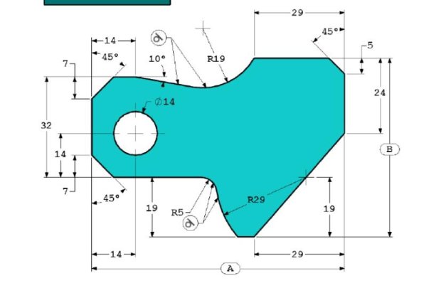
For each value of the geometric parameters A, B, and C, let's create the part and then bring out the mass of the part.
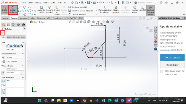
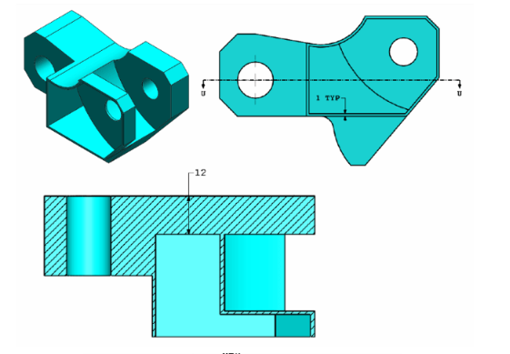
--> Case 1: A= 81.00; B=57.00; C= 43.00
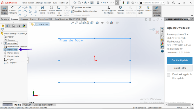
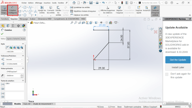
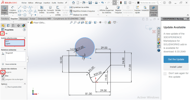
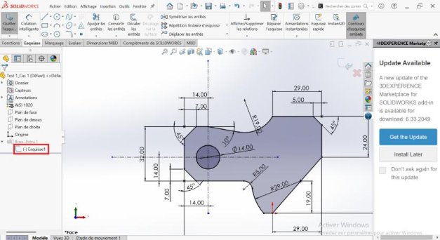
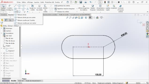
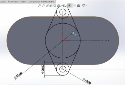
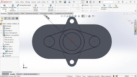
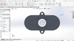
- Position yourself on the origin of the reference point and make a set of broken lines.
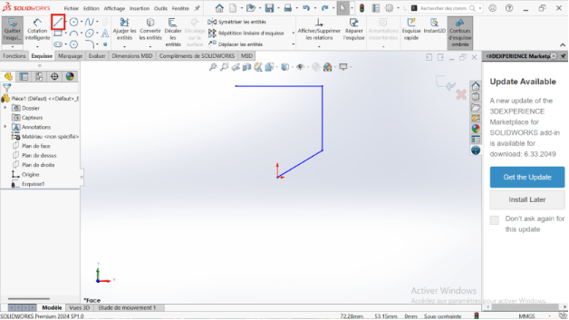
- Make the rating of the drawn lines.
- Click on the Point tool and position the center of the circle R29 (dimensioned at 19 mm from the origin of the reference).
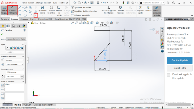
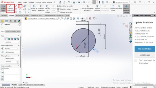
- Select the circle tool and create the circle corresponding to the point positioned previously.
-
Use the line tool to draw a horizontal line 19 mm from the horizontal axis passing through the axis of the marker.
-
Use the Adjust Features tool and delete the unnecessary portions of the circle.
-
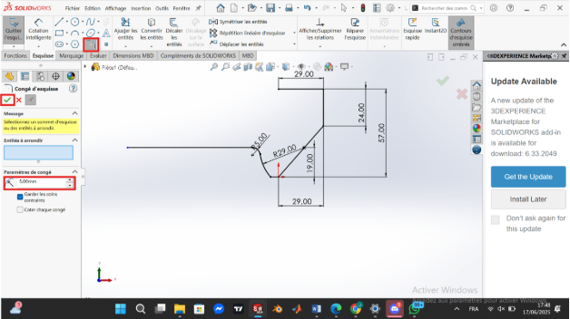
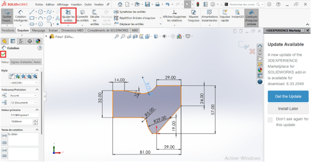
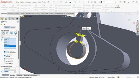
Take the sketch fillet tool to create the rounding R5 between the line drawn previously and the portion of the circle R29.
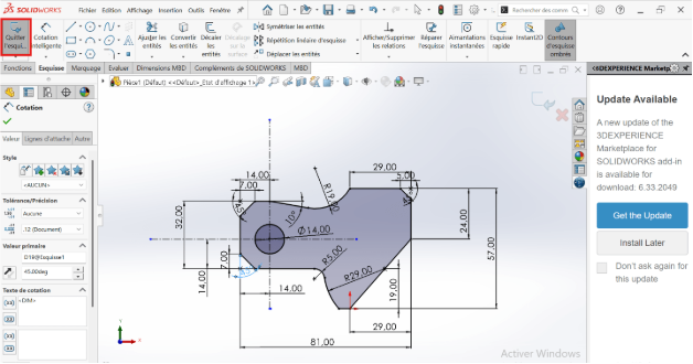
- Use the smart quote tool to quote dimension A.
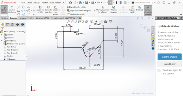
- Choose the line tool and create a set of broken lines.
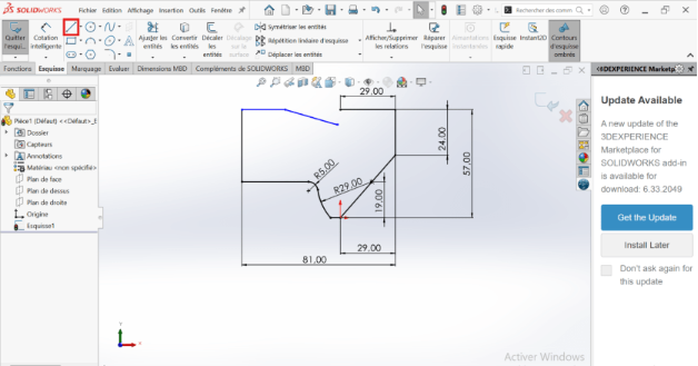
- Choose the smart dimension tool to dimension each line.
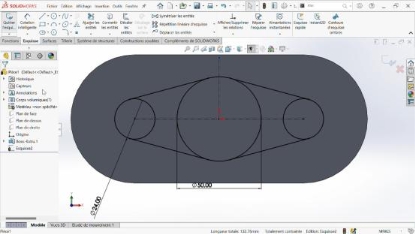
- Make a circle of R19 using the circle tool at any point in the workspace.
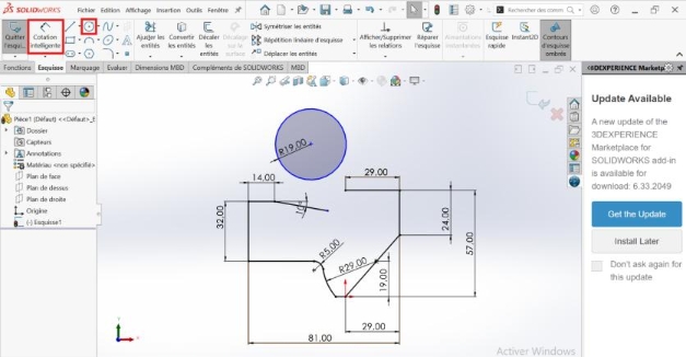
- Right-click and hold the Ctrl key to select the circle and the line inclined 10 degrees from the horizontal and apply the tangent constraint.
- Right click and hold the ctrl key to select the circle and… and apply the coincidence.
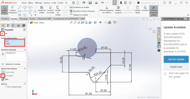
- Adjust the unnecessary portions of circle R19
- Draw the horizontal and vertical axes passing through the center of circle R7 (center of circle R14) and take the measurements.
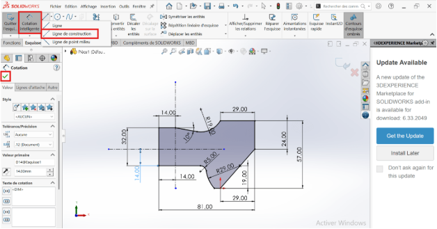
- Select the sketch chamfer tool and create the chamfer of 5 and 7
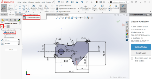
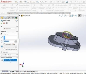
- Exit sketch
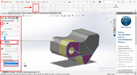
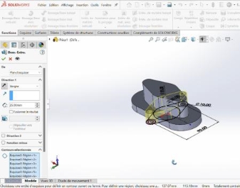
- Extrude to depth C in the features section with the boss extrusion tool.
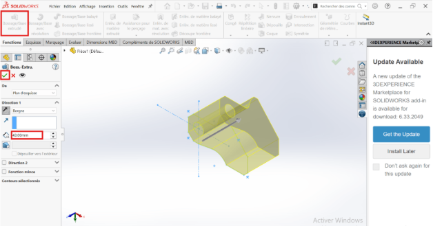
- Validate the extrusion
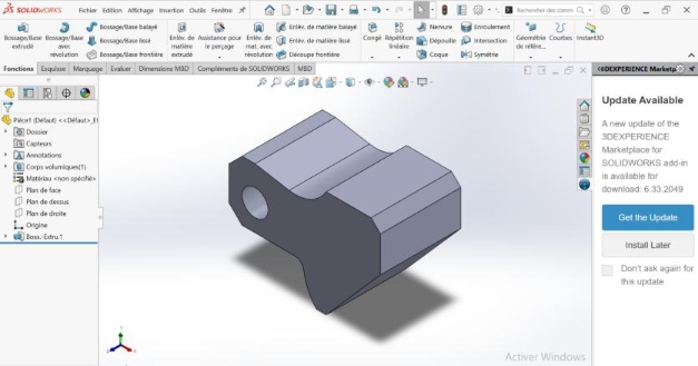
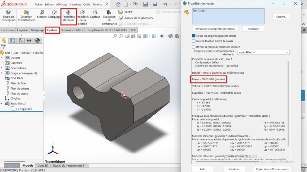
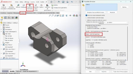
- Right click on material (unspecified) then click edit material, then apply and close
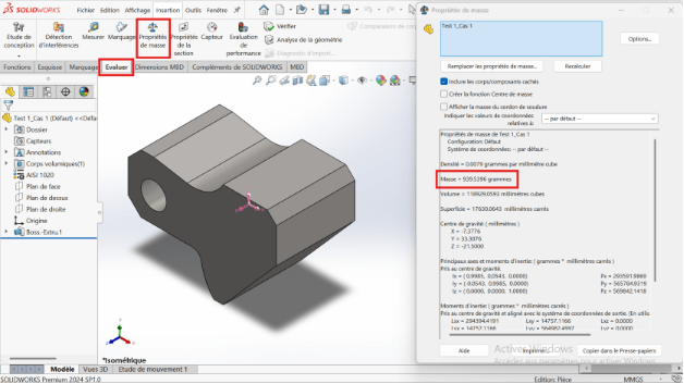
- Click on evaluate and choose mass properties, then configure
--> Case 2: A= 84.00; B=59.00; C= 45.00
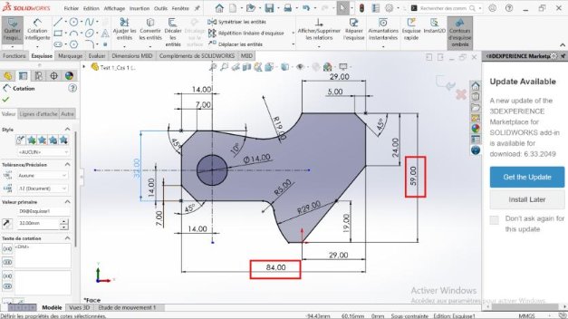
- Right-click on the recently created sketch and then edit it. This allows you to return to the base sketch to modify the A and B dimensions defined above.
- Double-click on dimension A=81mm then change it to A=84mm.
Double-click on dimension B= 57mm then change it to B=59mm.
- Then exit the sketch and return to the feature tools section.
Right click on Boss.-Extru.1 then edit the function, this allows you to modify the extrusion depth C.
In the feature manager, change the extrusion depth from C=43mm to C=45mm, then validate.
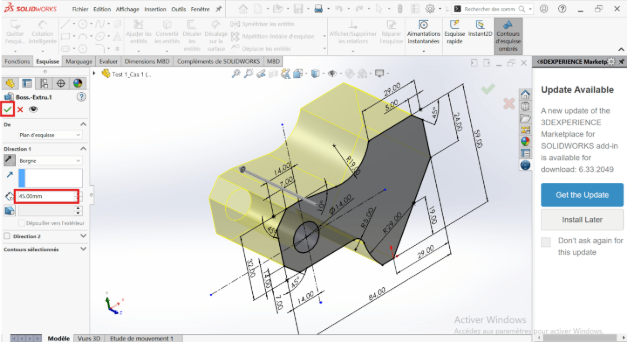
- After validation the mass of the part is m=1032.07g**
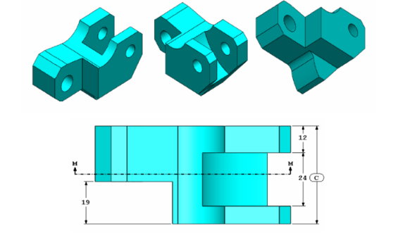
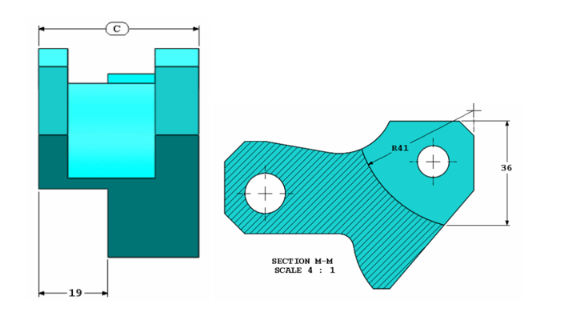
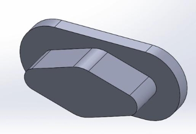
Let's use the part created in the previous question and modify it by removing material and changing the following parameters:
A= 86.00; B=58.00; C= 44.00
As before, repeat the process of modifying dimensions A, B, CD In this section, A= 86 mm; B=58 mm; C=44 mm.
- Modifying the basic sketch
- After modifying dimensions A, B and C, return to the basic sketch, still following the usual methodology.
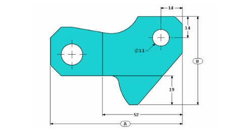
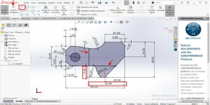
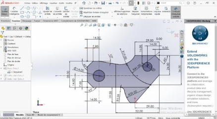
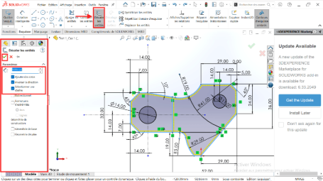
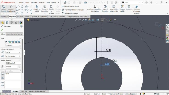
- Use the line tool to draw two lines, one vertical and one horizontal.
- Use the smart dimension tool to dimension these lines relative to a fixed line as identified in the screenshot below
-
Click on the point tool to place a point at any position on the sketch (this point consists of the intersection of the circle of radius R41 and the inclined line as shown in the screenshot).
-
Use the smart dimension tool to locate this point on the sketch (36 mm dimension framed by a rectangle on the capture).
-
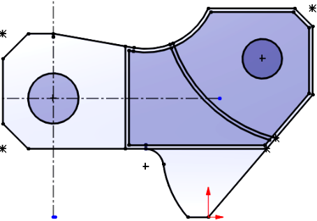
Click on the circle tool and then draw a circle of any radius passing through the recently defined point.
-
Click on the smart dimension tool to define the radius R41
-
Locate the center of the circle so that it lies on the vertical line (far right of the sketch)
-
Use the Adjust Features tool for unwanted portions of the circle.
-
Click on the circle tool then create a circle of any radius and arbitrary center
-
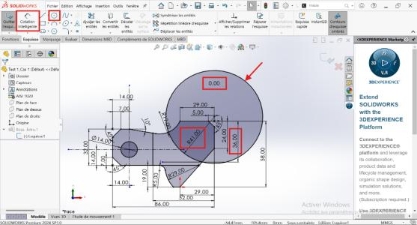
Use the smart dimension tool to dimension the circle drawn previously (diameter 11) then locate its center according to the dimensions in the capture below.
-
Exit sketch
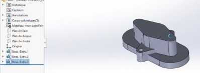
- Volume creation
-
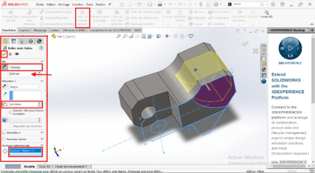
Click on the extrusion removal tool then select the entities to extrude (because these entities have the same extrusion depth).
-
Apply extrusion material removal settings.
- To validatethe execution of the function.
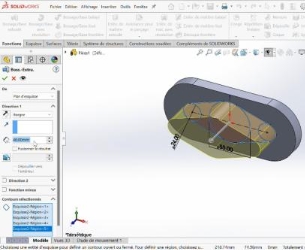
- Click on the sketch (return to the base sketch)
- Click on the extrude material removal tool and then select the entity to extrude.
- Apply the extrusion material removal settings (7 mm offset paying attention to the offset direction and 24 mm material removal depth)
- To validatethe execution of the function
- Click on the sketch in the future manager
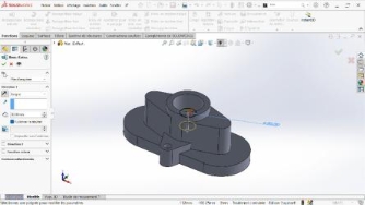
- Click on the extrusion material removal tool then select the entity to extrude (inside the 11 mm diameter circle).
- Apply the extrusion removal settings (change the blind option to through all).
- To validatethe execution of the function
- Click on Evaluate then select Mass Property

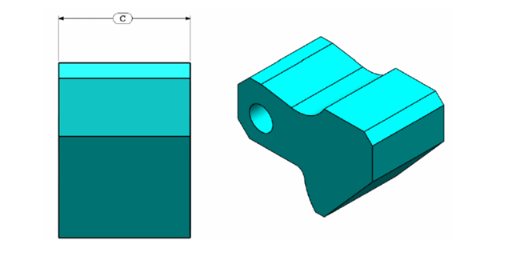
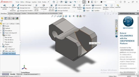
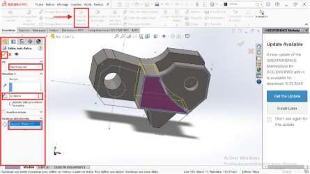
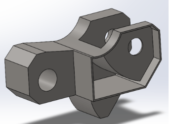
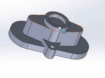
Let's use the part created in the previous question and modify it by adding a pocket.
- Editing the sketch
-
Right-click on the part and then click on the Edit Sketch icon
-
Click on the Offset tool
-
Select the entities to shift
-
Click the Adjust Features tool to remove unsuitable features
-
Exit sketch
- Volume creation
In this we will have to make two removals of material of different extruded depth (7mm and 32mm).
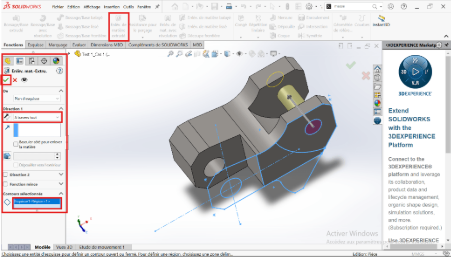
- Material removal depth 32 mm
- Select sketch 1
- Click on Function > Extruded Material Removal
- Select the relevant entity
- Apply material removal settings (depth, extrusion direction, etc.) in the Feature Manager
-
Then Validate
-
Material removal depth 7 mm
-
Click on Function > Material Removal
-
Select the relevant entity
-
Apply material removal parameters (depth, extrusion direction, etc.) in the Feature Manager
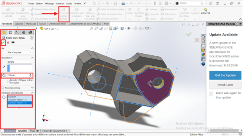
-
Then Validate
-
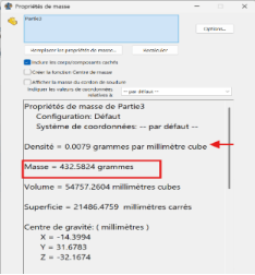
Mass properties
-
Design - Summary table of results
| Part | Specifications | Mass (g) |
|---|---|---|
| Part I-a | A = 81,00 ; B = 57,00 ; C = 43,00 | 939,54 |
| Part I-b | A = 84,00 ; B = 59,00 ; C = 45,00 | 1032,32 |
| Part II | A = 86,00 ; B = 58,00 ; C = 44,00 + Material removal | 628,18 |
| Part III | Pocket feature added | 432,58 |
Assembly
Unit systems: MMGS (millimeter, gram, second);
Decimals: 2
Origin of the assembly: As shown in the picture
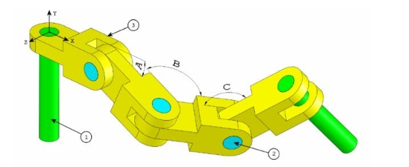
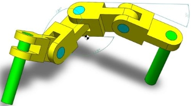
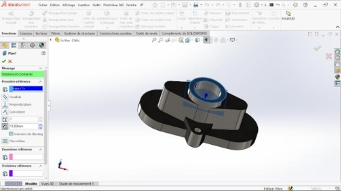
Let's build this assembly in SOLIDWORKS (Chain Link Assembly)
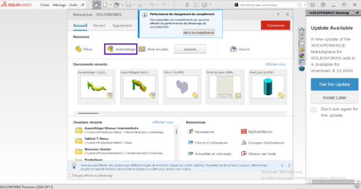
- Launch the software
- Select the Assembly icon or from the main menu, click File > New > Assembly.
- A new assembly environment opens, with a specific creation tree (FeatureManager)
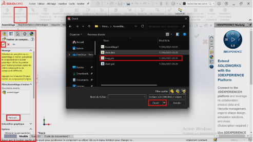
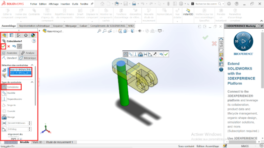
- Inserting a part
- Click the Insert Components tool: a recent folder tab will open or in the PropertyManager click browse
- Select part 1 titled “long_pin” then click on open
- Use the axes (X, Y and Z) to orient the part to be inserted then validate
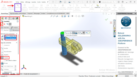
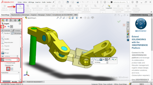
- Assembly of parts (definition of constraints)
- Also insert part 3 titled “chain_link”
- Click on the Constraint tool
- Select the two faces to be constrained or linked
- Click on coaxial
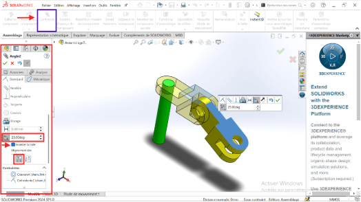
- Insert part 2 “Short_pin” again
- Add the Coaxial constraint between the two holes
- Add the Coincidence constraint between surfaces that must be in contact
- Select the affected faces to specify a 25° angle constraint
- Insert part 3 titled “Chain_link”
- Add the Coaxial constraint between the hole and the surface of revolution of part 3
- Add the coincidence constraint to prevent translation of part 3
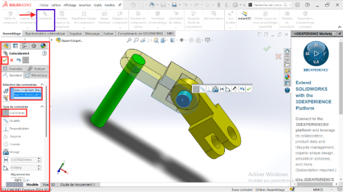
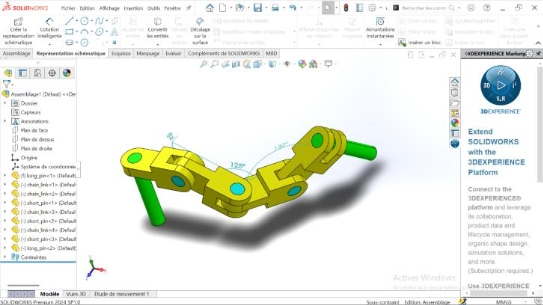
- Insert the second part 3 “Chain_link” again
- Add the necessary constraints and specify the angle constraint as 125°
- Insert part 2 titled “short_pin”
- Add the necessary constraints
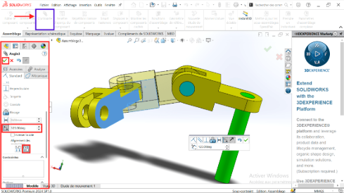
- Insert part 2 “Short_pin” again
- Add the necessary constraints and specify the angle constraint as 130°
- Insert part 2 titled “short_pin”
- Add the necessary constraints
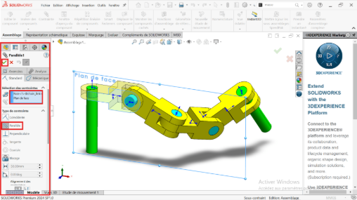
When the first part is inserted in the present way, it is necessary to constrain the axes with the Plan (front plane, right plane) of one of the parts of the assembly
- Add a parallel constraint: Right-click on the front plane and click the constraint icon
- Select the side face of the first part 3 insert
- Click on Validate
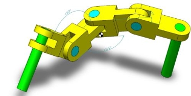
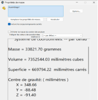
A = 25 degrees; B = 125 degrees; C = 130 degrees
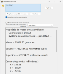
A = 30 degrees; B = 115 degrees; C = 135 degrees
Assembly - Summary table of results
| Center of mass coordinates (mm) | |||
|---|---|---|---|
| X | Y | Z | |
| A = 25 degrees; B = 125 degrees; C = 130 degrees | 348.66 | -88.48 | -91.40 |
| A = 30 degrees; B = 115 degrees; C = 135 degrees | 339.43 | -98.39 | -52.36 |
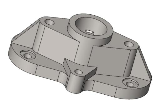
Bonus
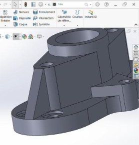
- Objective
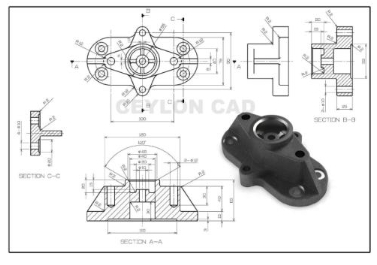
This bonus section consists of making the part below and applying the material ''AISI1020 Steel with density 0.0079 g/mm^3
- Summary
This part was made using different functions namely: extruded boss, extruded material removal, drilling assistance, rib, symmetry fillet, circular repetition.
-
Extruded boss (1)
-
Extruded material removal (2)
-
Drilling assistance (3)
-
Leave (4)
-
Linear repeat circular repeat option (5)
-
Rib (6)
-
Reference geometry (7)
-
Symmetry (8)
-
Production of the piece
- Create a sketch on the front plane and make the base of the part using the groove tool
-
Make a 15mm extruded boss
-
Take one face of the resulting part and create a new sketch on it
-
Draw two construction lines (both perpendicular to the origin), use the circle, dimension and symmetry tools to obtain the following sketch
-
 Make a 40 mm extruded boss to obtain the part below
-
Take the second face of the first boss and create a new sketch to extrude by 25mm
-
We obtain the part below
-
Create a sketch on the top surface of the second extruded boss and use the 'Convert Entities' tool to convert the face, creating a circle with a diameter of 40mm; this sketch will be extruded by 10mm
-
 Make a 10mm extruded boss, we obtain the following part
 -
 Use the Ø40mm circle and make an extruded material removal through all
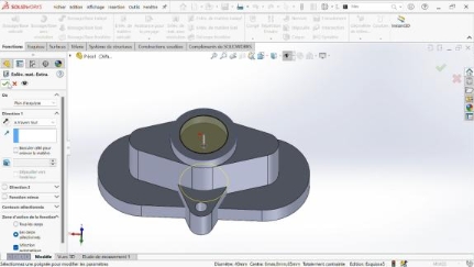
-
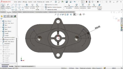
Use the "reference geometry" function to create a plane parallel to the flat surface obtained after the previous operation and offset by 15 mm from it towards the as
-
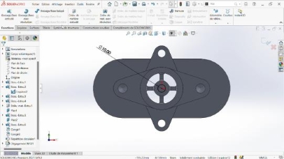
 On this created plan, create a new sketch on which we draw a circle of Ø20mm which will be extruded by 20mm
 -
On the same plane we create a new sketch, we convert the last two edges to an interior circular and we use a construction line of origin, the origin of the reference point and we use it to symmetrize a line spaced 2.5 mm from the construction line. This sketch is to be extruded
-
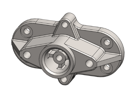
After extrusion, the result is as follows
-
 We make 2mm cuts
 -
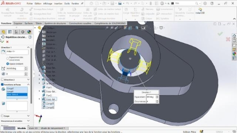
 We use the circular repeat function located in the drop-down file of the linear repeat function and we repeat the two previous functions 4 times over 360 degrees
 -
 Now we move on to drilling the holes using the "Drilling Assistance" function. First, the two M12 blind holes
 -
 A circle is created on the face as shown in the figure below and an extruded material removal is made
 -
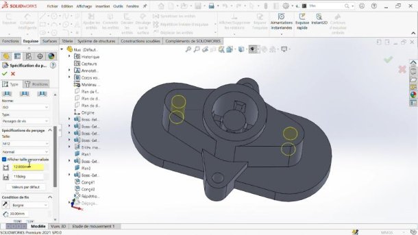
Let's continue with the drilling. Now we need to make four counterbores. Before using the drilling function, we need to create a sketch and enter the locations of the counterbored holes. Here's the sketch
-
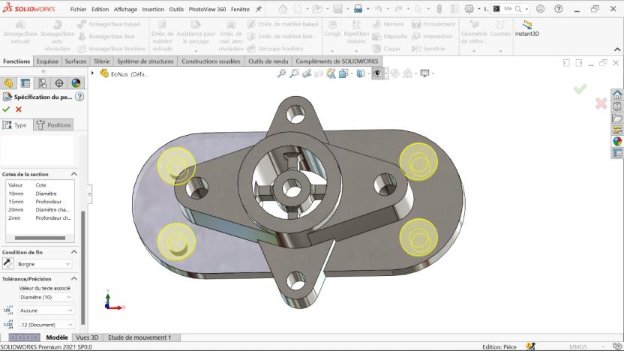 We now create the 10 mm counterbores
 -
Move on to the rib creation step. We create the following sketch. In our plan, the sketch is mainly created on the top plane.
-
 We use the rib function, and we admire our created rib
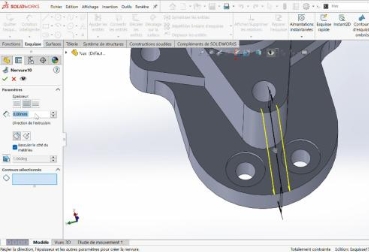
-
By making a symmetry of the first rib with respect to the plane on the right we obtain the second rib
-
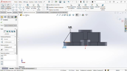
 We create a sketch on the back face as shown in the figure below, we make a removal of extruded material of 3mm
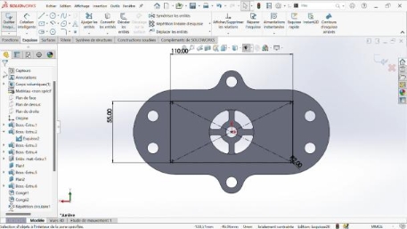
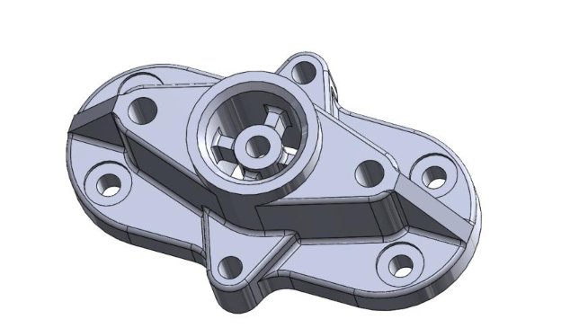
-
Moving on to finishing. We finish with the fillets and chamfers. We edit the material. We obtain the requested part.
-
Perspectives
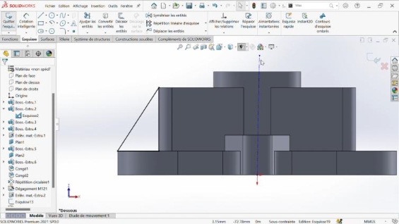 Another solution to create the rib is to create a right triangle and extrude it, using the midplane option. Here is the sketch.