2nd Test
Objectives
In industries like automotive, aviation, and rail, black boxes are essential for monitoring vehicle activity. These systems record various parameters; in aircraft, for instance, they log pilot communications and flight data such as speed, altitude, and spatial orientation using advanced sensors. This information is crucial for crash investigations.
For the Tekbot Robotics Challenge, your task is to design a black box capable of recording speed and spatial position data using a gyroscope and accelerometer. This data must be transmitted in real time via I2C to a control station where it will be displayed on an LCD screen. The project has two components: a data-collecting/transmitting black box and a control station for receiving and displaying the data. You’ll present the project through a video showing the box moving in space with its motion data visualized on the control station.
Technical Requirements:
- Reuse the same sensor as the previous project, meaning success depends on your earlier work.
- Use Atmega328P microcontrollers directly, not Arduino boards.
- Create electronic schematics using KICAD and design/produce your own PCBs.
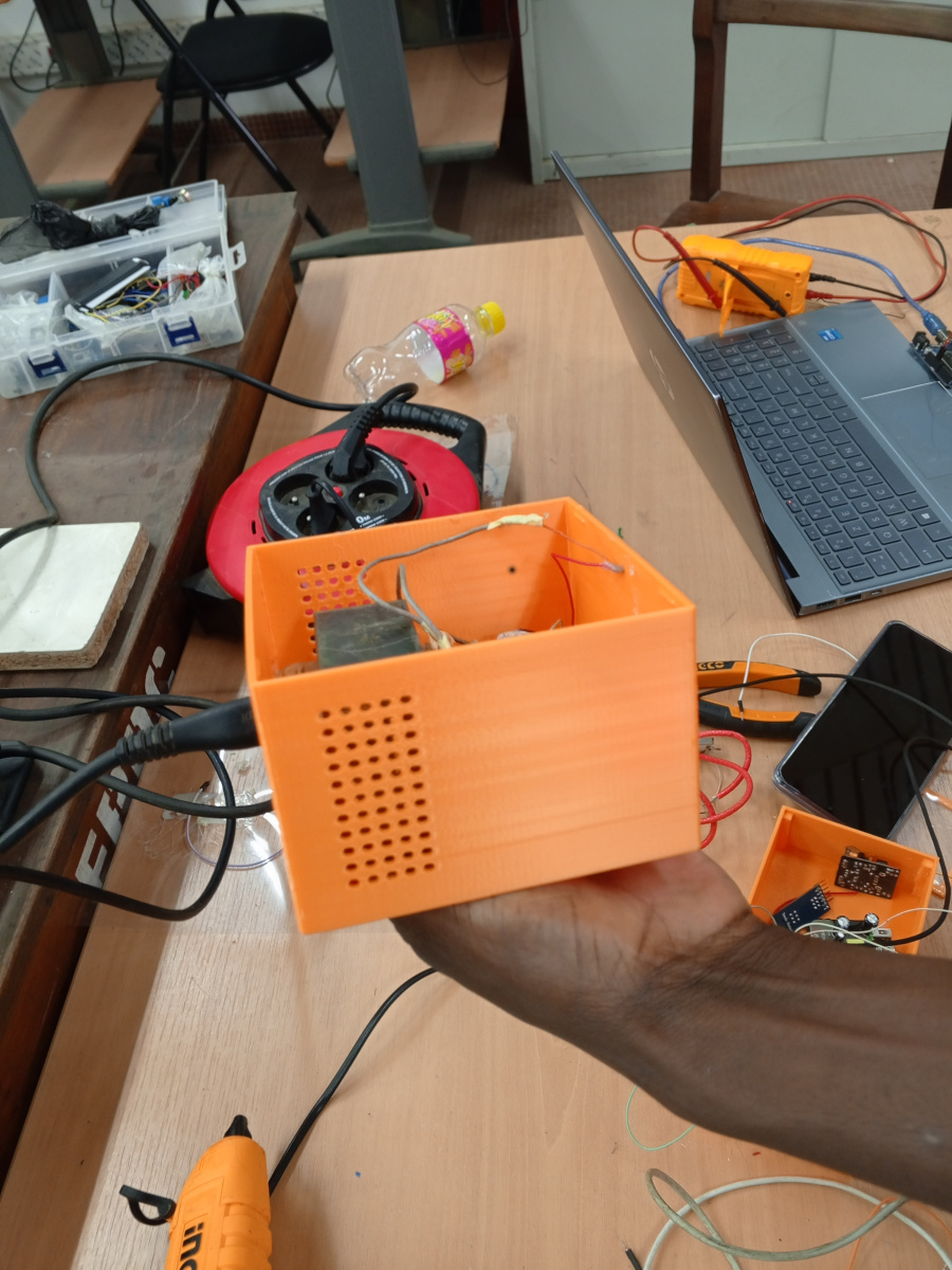
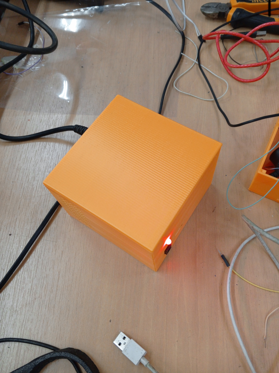
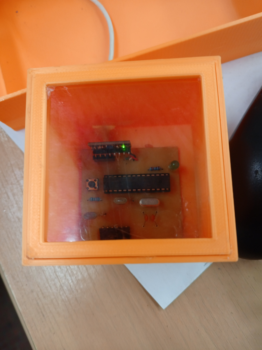
- Build a 7 cm cube (the black box) with an open top if the material is opaque, to view the circuit inside.
- Design your own power supply (external to the cube).
- Create an I2C bus where the microcontroller inside the cube is the only master, and the sensor (inside the cube) and control station microcontroller are slaves. The LCD should operate in 4-bit mode.
- As before, move the cube in all directions and display real-time data on the LCD.
- Document your work on the assigned GitHub repository.
Summary
This documentation describes the design and fabrication of two custom PCBs:
- One embedded inside a 7×7 cm cube (the black box) responsible for sensing and sending data over I2C.
- One external circuit acting as a control station that displays the data on an LCD in 4-bit mode and provides user feedback through LEDs.
The boards were designed using KiCad and produced via UV exposure and chemical etching. Power supply and programming were handled via custom connectors and FTDI interfaces.
Files available for download
Download the KiCad and Arduino files by following these links :
KiCad
-
Black box : Black box KiCad file
-
Control station : Black box : Control station KiCad file
Arduino
-
Black box : Black box Arduino file
-
Control station : Control station Arduino file
Materials
List of components used for both the black box and signaling box.
Black Box Circuit
Below is the list of the different components used for the design of the circuits in kiCad.
| Component | Quantity | Description |
|---|---|---|
| ATmega328P | 1 | Microcontroller |
| 16MHz Quartz | 1 | Clock source for the microcontroller |
| 22pF Capacitors | 2 | Polarization capacitors for the quartz |
| MPU 6050 | 1 | Gyroscope and accelerometer sensor |
| Push Button | 1 | Reset button for the microcontroller |
| 10k Resistor | 1 | Pull-up resistor for the reset button |
| LED | 1 | Indicator LED on pin 13 |
| Connectors | 1 | For FTDI programmer and signaling box connection (I2C connection) |
Signaling box
| Component | Quantity | Description |
|---|---|---|
| ATmega328P | 1 | Microcontroller |
| 16MHz Quartz | 1 | Clock source for the microcontroller |
| 22pF Capacitors | 2 | Polarization capacitors for the quartz |
| MPU 6050 | 1 | Gyroscope and accelerometer sensor |
| Push Button | 1 | Reset button for the microcontrolleur |
| 10k Resistor | 1 | Pull-up resistor for the reset button |
| LED | 1 | Indicator LED on pin 13 |
| Connectors | 3 | For FTDI programmer, black box connection (I2C connection), and LCD (in 4 bits mode) |
| N-channel MOSFET | 1 | Protection against polarity reversal |
| LEDs | 6 | Indicator LEDs for movement directions of black box |
Tools and software:
- KiCad for schematic and PCB design
- UV exposure box
- Ferric chloride (FeCl₃) for etching
- Drill press for holes
- Soldering station
Process
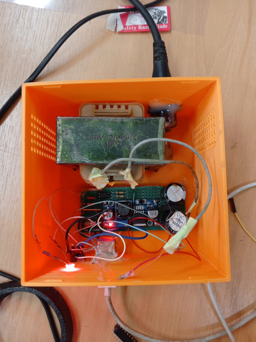
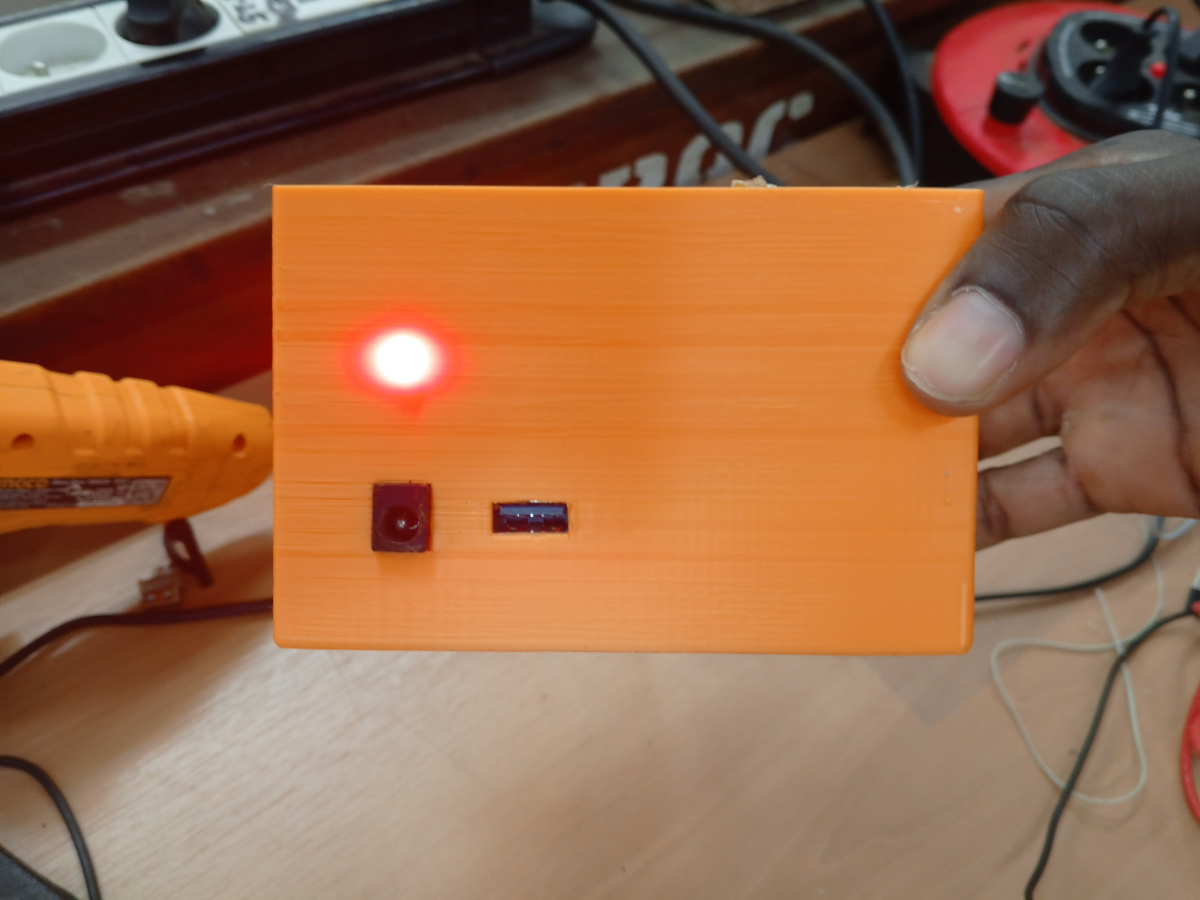
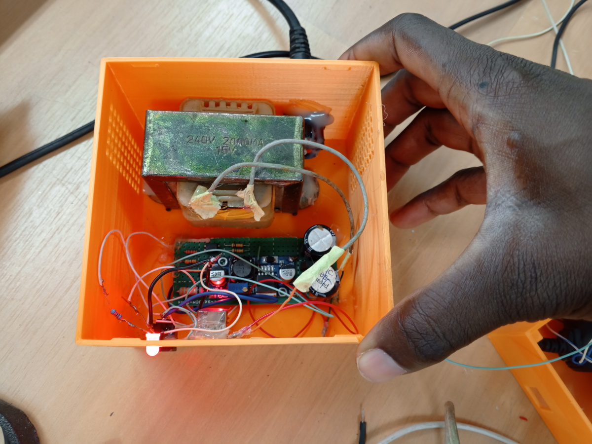
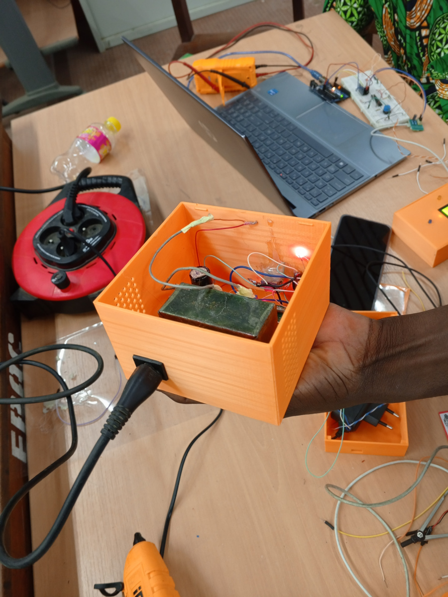
Power Supply Design
In this test, we were asked to design our own power supply. So, we used the power supply built during the first test.
Here are the Pictures showing it :
 |  |  |
|---|---|---|
 |  |  |
Hardware design
Circuit Design Process
-
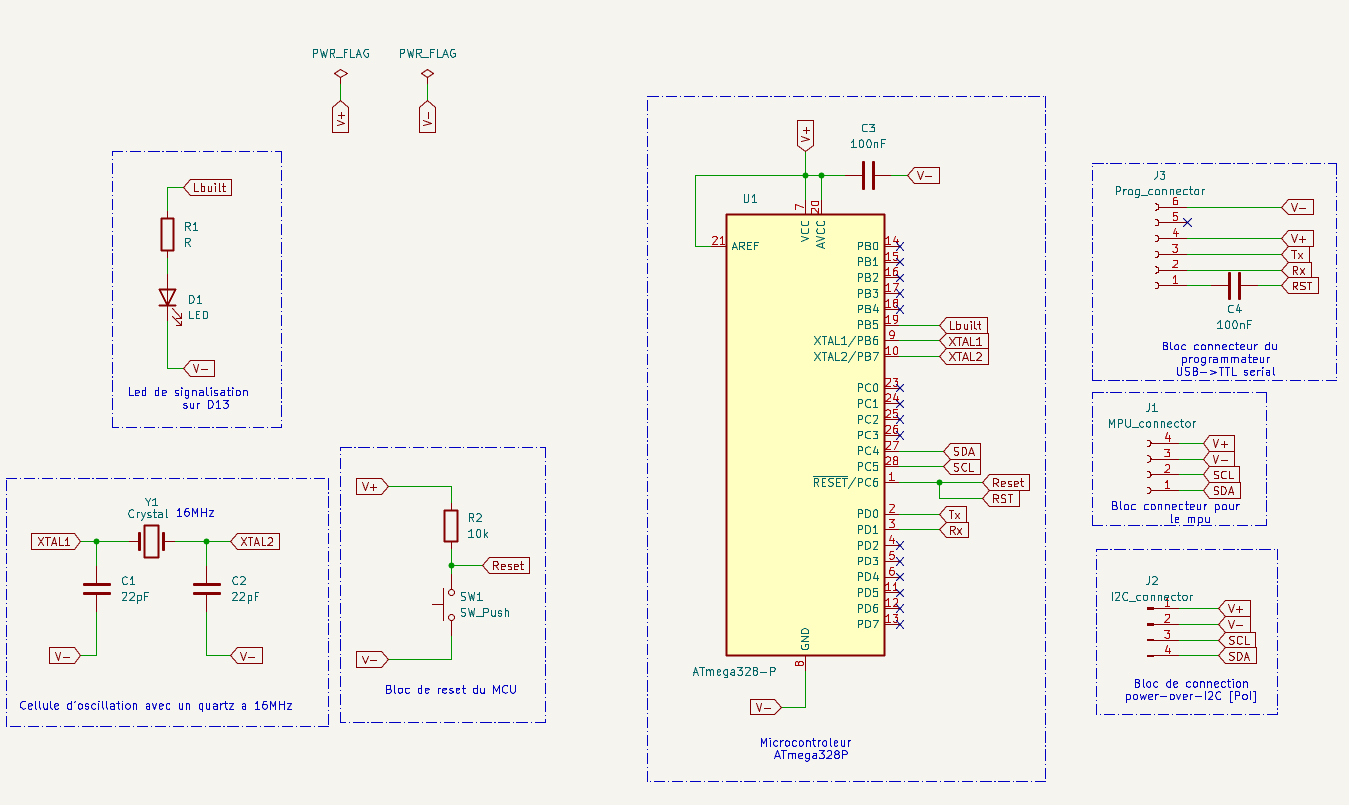
Schematic Design (KiCad):
-
Each circuit started with the basic ATmega328P configuration:
- Clock circuit: 16 MHz crystal + 2×22pF capacitors.
- Reset circuit: Push button with 10kΩ pull-up.
- Status LED on digital pin 13.
- FTDI programming header (TX, RX, GND, VCC, DTR).
-
For the Black Box:
- I2C connection to MPU6050.
- Header for I2C output to control station.
-
For the Control Station:
- I2C input from Black Box.
- LCD interface in 4-bit mode.
- 6 LEDs for visual feedback on motion along 6 directions.
- Polarity protection using a N-channel MOSFET.
-
-
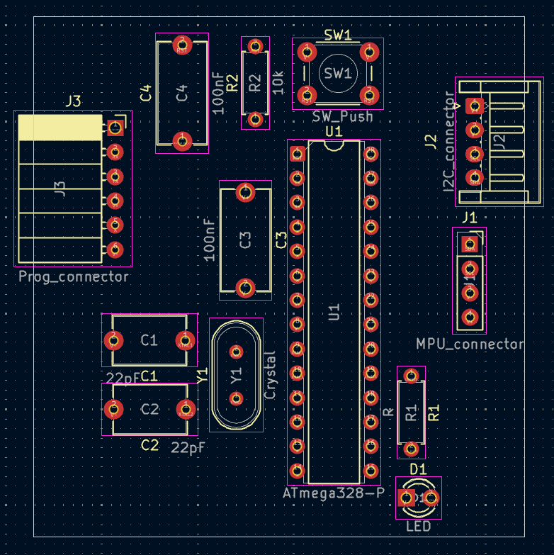
PCB Layout:
- All components were placed to ensure compact design, short traces, and accessible connectors.
- Decoupling capacitors placed near power pins.
- Ground plane added to reduce noise.
-
Exporting and Printing:
- Layouts were exported as mirrored PDF files and printed on transparent film for UV exposure.
PCB Fabrication Process
-
UV Exposure:
- The printed film was placed over a photosensitive copper-clad board.
- Exposed to UV light for ~8 minutes.
-
Developing:
- Board developed in sodium hydroxide solution to reveal copper traces.
-
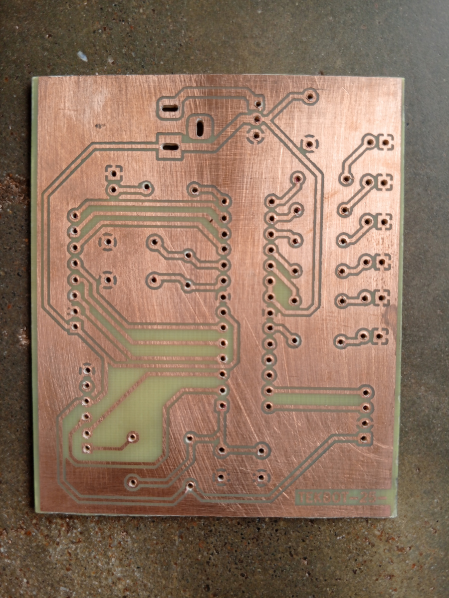
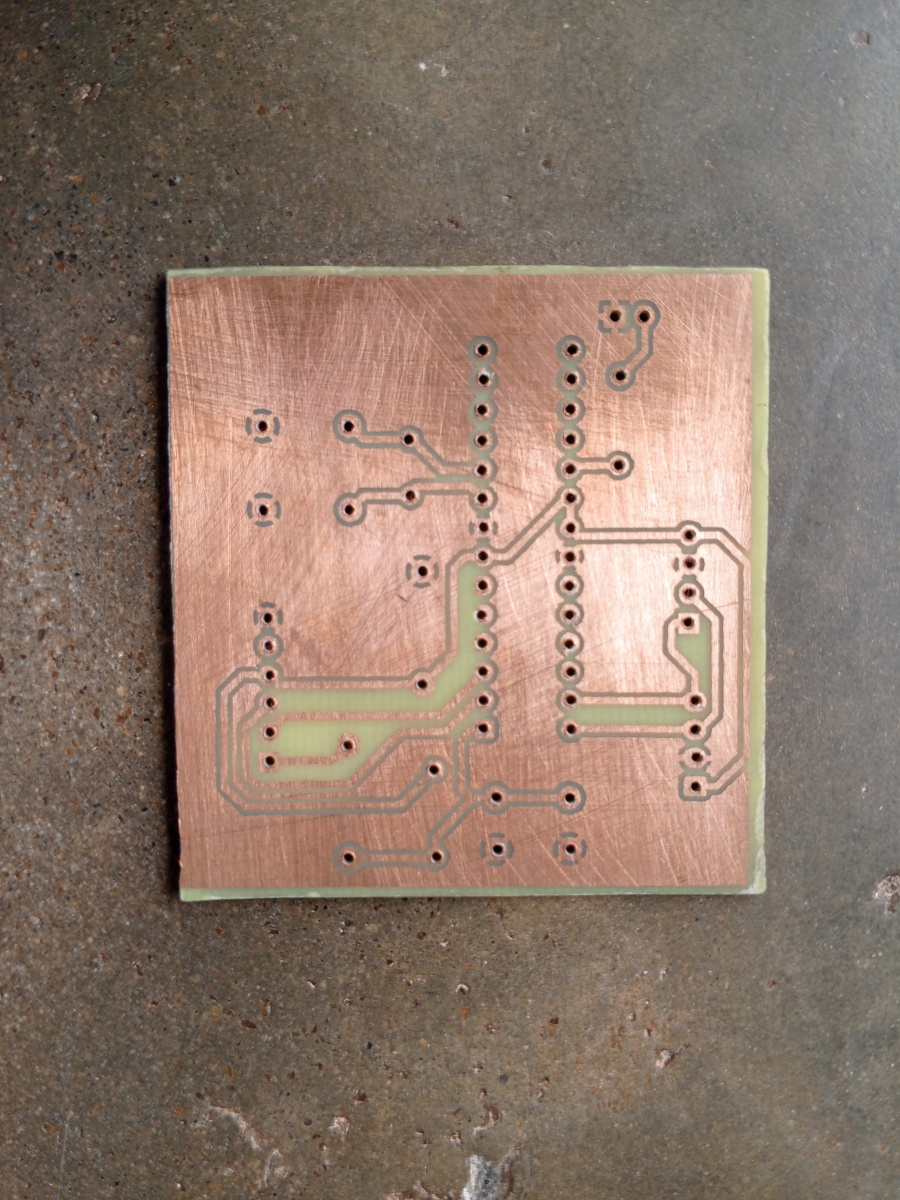
Etching:
- Ferric chloride was used to remove unprotected copper.
-
Drilling and Soldering:
- Holes drilled for through-hole components.
- Components soldered in place with attention to orientation and clearance.
Boite noire
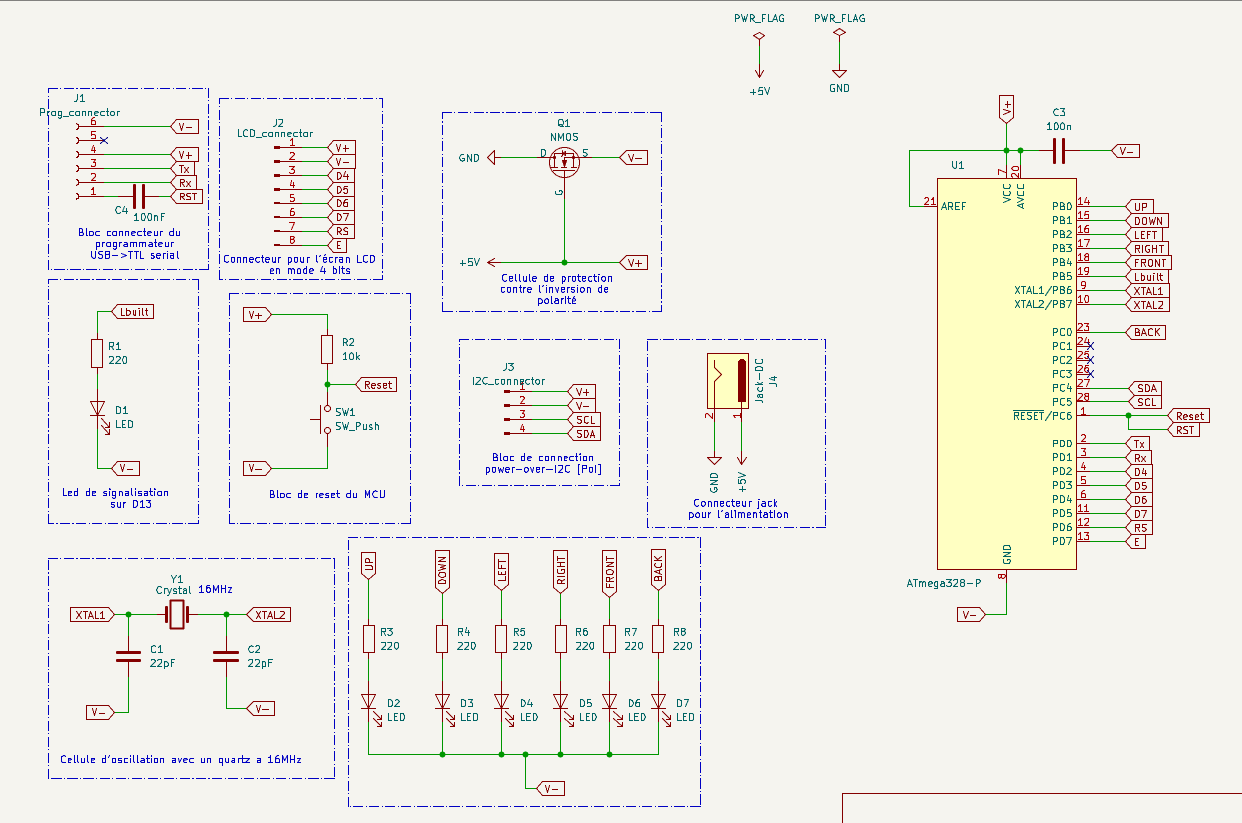
- Schematic capture:
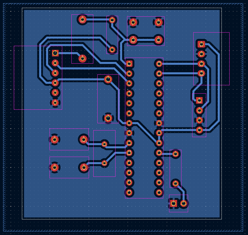
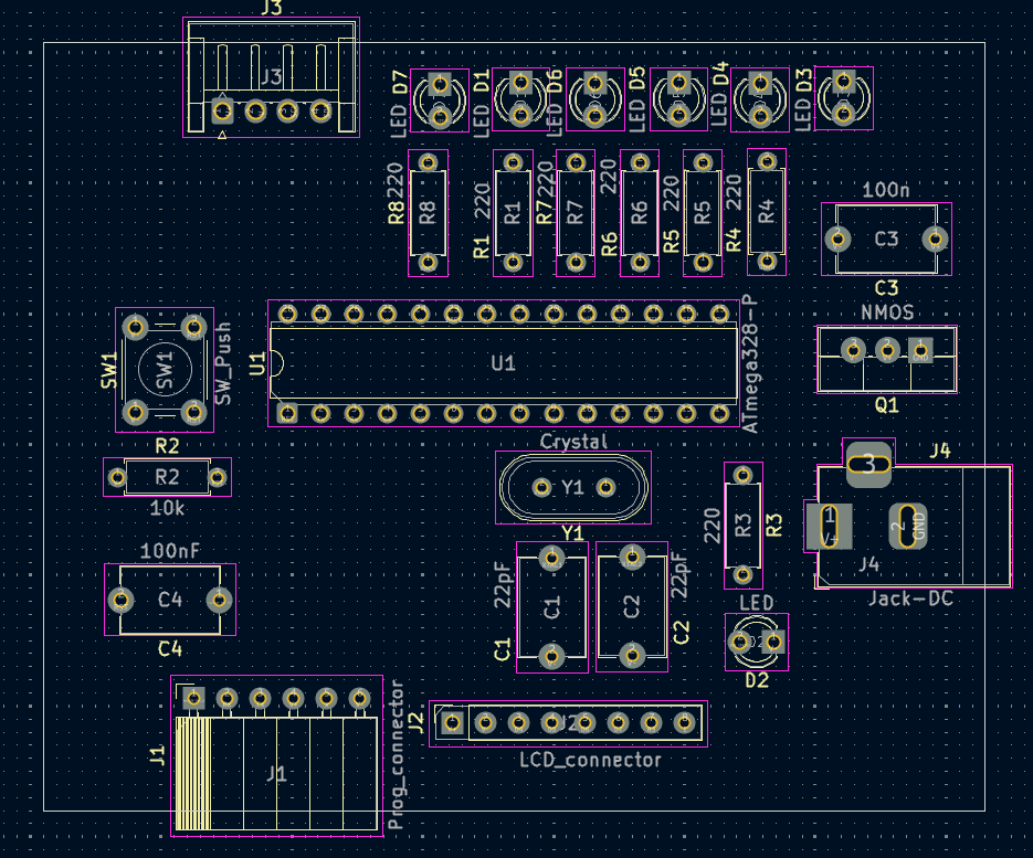
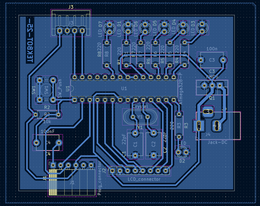
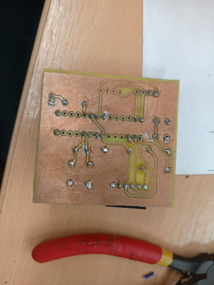
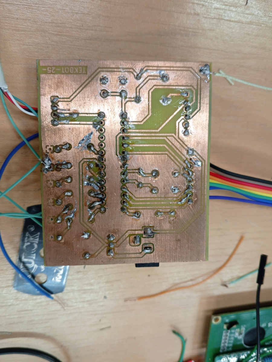
- Printed circuit board overview :
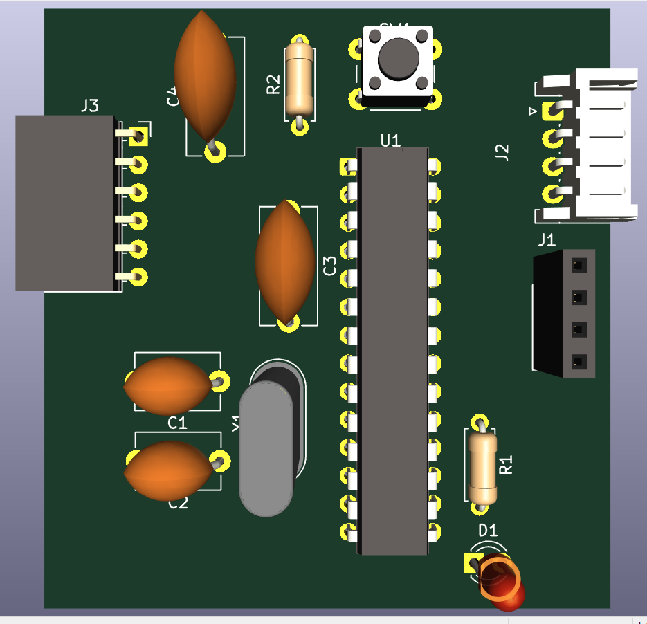
- 3-D render of printed circuit board :
Boite de signalisation
- Schematic capture: :
- Printed circuit board overview :
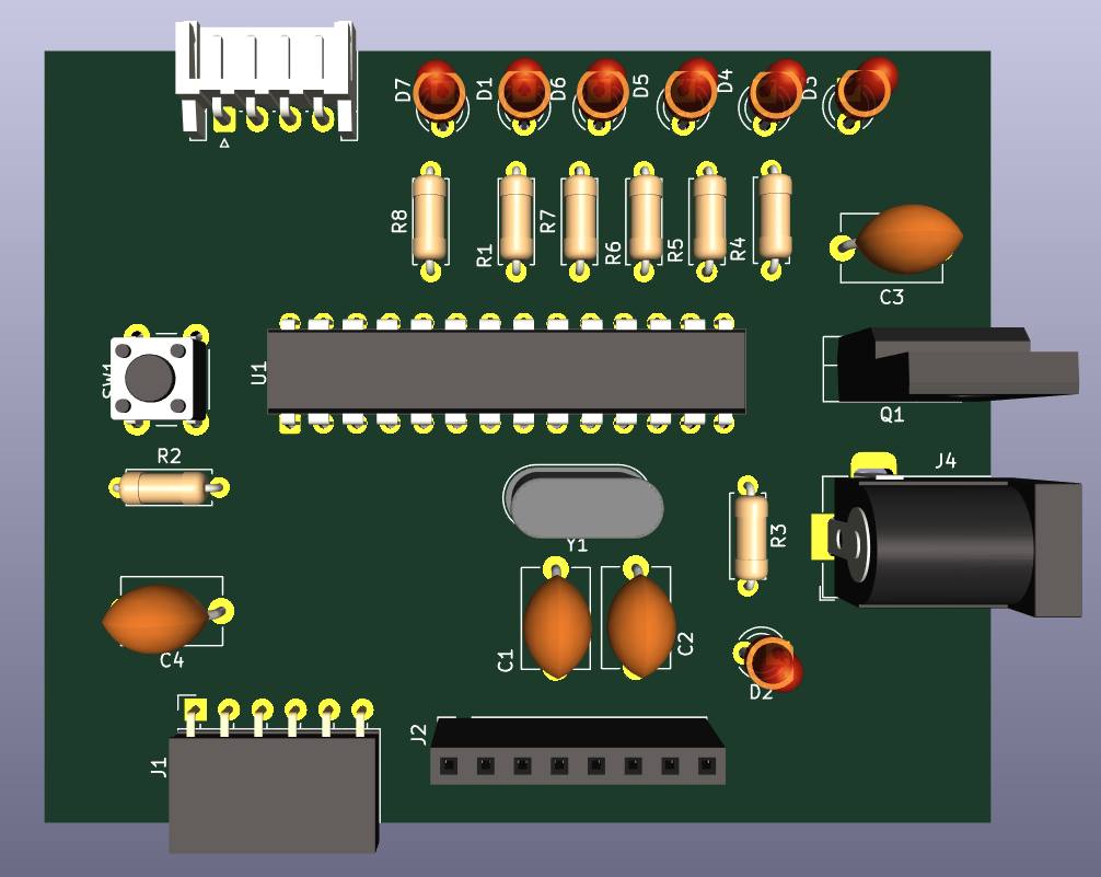
- 3-D render of printed circuit board :
- Time-lapse of PCB etching
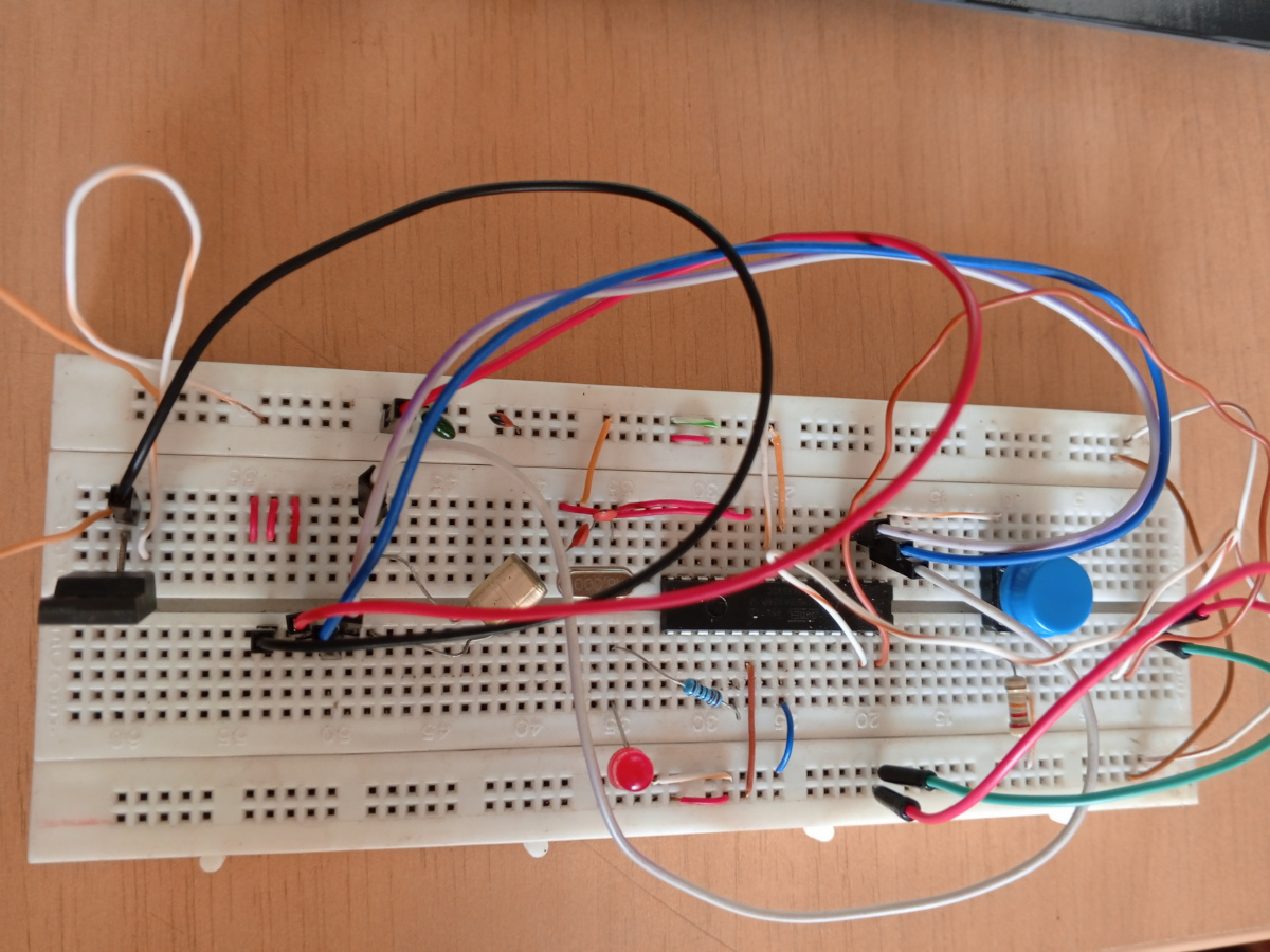
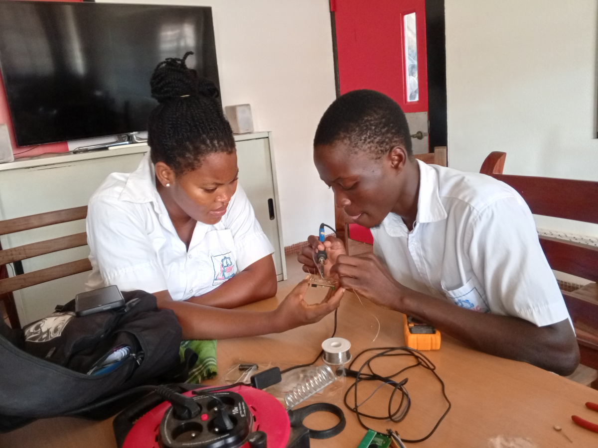
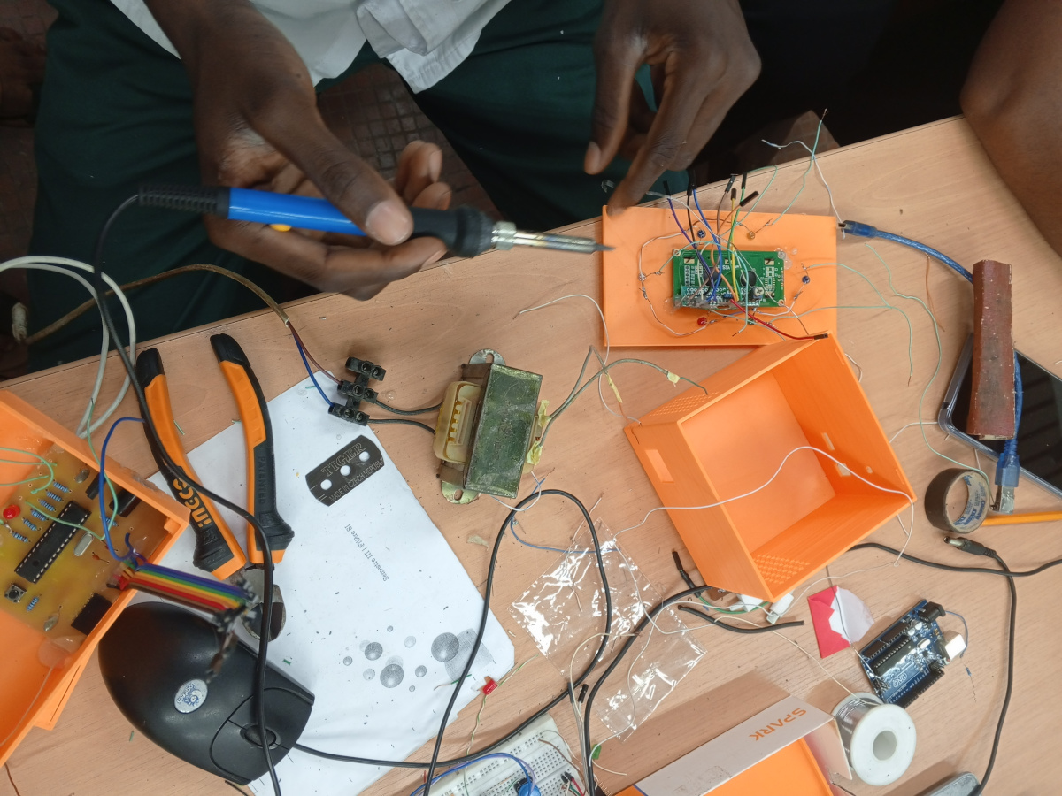
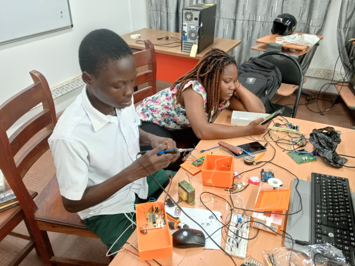
- Assembly of components
- Test of LED indicator and MPU movement detection
- Data shown in real time on LCD display
Difficulties and Solving Approach
| Problem | Solution |
|---|---|
| Noise in sensor readings due to poor grounding | Added full ground plane and decoupling capacitors |
| Difficulty programming ATmega328P directly | Used FTDI interface with DTR for smooth uploading |
| LCD flickering | Implemented delay and correct 4-bit wiring |
| Power polarity inversion risk | Added MOSFET-based protection circuit |
| Manual drilling imprecision | Used small drill bits with guided PCB holders |
Software design
Black box
1. Includes et Définitions
Bibliothèques incluses
-
#include "I2Cdev.h"et#include "MPU6050_6Axis_MotionApps20.h": Ces bibliothèques sont spécifiques au capteur MPU6050, particulièrement pour utiliser son processeur de mouvement numérique (DMP). -
#include <Wire.h>: Bibliothèque Arduino standard pour la communication I2C (Inter-Integrated Circuit), essentielle pour communiquer avec le MPU6050 et la station de contrôle. -
MPU6050 mpu;: Crée une instance de l'objet MPU6050. -
#define CONTROL_STATION_ADDRESS 0x20: Définit l'adresse I2C de la station de contrôle, qui est l'esclave dans cette communication.
2. Structure de données et Variables
Structure MPUData
struct MPUData : Cette structure est conçue pour contenir toutes les données pertinentes du MPU6050 et les informations de mouvement calculées. Cette structure doit correspondre à celle définie dans le code de la station de contrôle pour un échange de données correct.
MPUData mpuData; : Une instance de la structure MPUData pour stocker les données avant de les envoyer.
Conteneurs de données MPU6050
Quaternion q;: Stocke les composants du quaternion.VectorInt16 aa;: Stocke les données brutes de l'accéléromètre.VectorInt16 aaWorld;: Stocke l'accélération corrigée de la gravité dans le référentiel mondial.VectorInt16 aaReal;: Stocke les mesures du capteur d'accélération sans gravité.VectorInt16 gy;: Stocke les mesures du capteur gyroscope.VectorFloat gravity;: Stocke le vecteur de gravité.float ypr[3];: Un tableau pour stocker les angles de lacet, tangage et roulis.
Variables de détection de mouvement
VectorInt16 prevAccel = { 0, 0, 0 };: Stocke les valeurs d'accélération précédentes pour calculer les différences d'accélération pour la détection de mouvement.unsigned long prevTime = 0;: Stocke l'horodatage précédent pour les calculs deltaTime.float movementThreshold = 1.0;: Un seuil configurable (en m/s²) pour déterminer si un mouvement est suffisamment significatif pour être détecté.byte lastMovementDetected = 0;: Une variable globale pour stocker le dernier code de mouvement reconnu. C'est la valeur envoyée à la station de contrôle. Les codes de mouvement vont de 0 (Pas de mouvement/Inactif) à 6 (Arrière).
3. Fonction setup()
void setup() {
  // Initialize Wire as Master for both MPU6050 and Control Station communication
  Wire.begin(); // Initializes the Wire library, setting the Arduino as an I2C Master.
  Wire.setClock(400000); // Sets the I2C communication speed to 400kHz (fast mode).
  pinMode(LED_BUILTIN, OUTPUT); //Configures the built-in LED as an output, likely for status indication.

  // Initialize Serial for debugging (via USB-TTL if standalone ATMEGA)
  Serial.begin(115200);
  Serial.println(F("Initializing Black Box as I2C Master..."));
  Serial.println(F("Initializing MPU6050..."));

  // Initialize and test MPU6050 connection
  mpu.initialize();
  if (!mpu.testConnection()) { /* Checks if the MPU6050 connection is successful. If not, it prints an error and halts execution.*/
    Serial.println("MPU6050 connection failed!");
    while (1); // Stop execution if connection fails
  }
  Serial.println("MPU6050 connected.");

  // Initialize the MPU6050 DMP
  devStatus = mpu.dmpInitialize(); // Initializes the MPU6050's Digital Motion Processor (DMP).

  // Set default calibration offsets (adjust if needed)
  /*Sets default calibration offsets for the gyroscope and accelerometer.
   These might need adjustment for specific sensor units.*/
  mpu.setXGyroOffset(0);
  mpu.setYGyroOffset(0);
  mpu.setZGyroOffset(0);
  mpu.setXAccelOffset(0);
  mpu.setYAccelOffset(0);
  mpu.setZAccelOffset(0);

  if (devStatus == 0) {//Checks if DMP initialization was successful.
    // Auto-calibration (may take a few seconds)
    Serial.println(F("Calibrating MPU6050... Do not move."));
    mpu.CalibrateAccel(6);
    mpu.CalibrateGyro(6);
    mpu.PrintActiveOffsets(); // Print offsets if you want to note them
    Serial.println(F("Calibration complete."));

    mpu.setDMPEnabled(true);
    DMPReady = true;
    packetSize = mpu.dmpGetFIFOPacketSize(); //Gets the expected packet size from the DMP.
    Serial.println(F("DMP ready."));
  } else {
    Serial.print("DMP initialization failed with code: ");
    Serial.println(devStatus);
    while (1); // Stop execution
  }

  // Initialize previous time for deltaTime calculation
  prevTime = millis();

  Serial.println(F("Black Box Master ready. Searching for Control Station..."));

//************************************************************
    digitalWrite(LED_BUILTIN, HIGH);  // turn the LED on (HIGH is the voltage level)
    delay(1000);                      // wait for a second
    digitalWrite(LED_BUILTIN, LOW);   // turn the LED off by making the voltage LOW
    delay(1000);                      // wait for a second

//************************************************************
}
4. Fonction loop()
// LOOP FUNCTION
// ================================================================
void loop() {
  if (!DMPReady) return; // Make sure DMP is ready before proceeding

  if (mpu.dmpGetCurrentFIFOPacket(FIFOBuffer)) { // Check if a new packet is available in FIFO
    // Read current time and calculate deltaTime (for future use, not directly for detection here)
    unsigned long currentTime = millis();
    float deltaTime = (currentTime - prevTime) / 1000.0;
    prevTime = currentTime;

    // Retrieve DMP data
    mpu.dmpGetQuaternion(&q, FIFOBuffer);
    mpu.dmpGetGravity(&gravity, &q);
    mpu.dmpGetAccel(&aa, FIFOBuffer);
    mpu.dmpGetLinearAccel(&aaReal, &aa, &gravity);
    mpu.dmpConvertToWorldFrame(&aaWorld, &aa, &q); // Converts acceleration to the world frame, removing gravity.
    mpu.dmpGetGyro(&gy, FIFOBuffer);
    mpu.dmpGetYawPitchRoll(ypr, &q, &gravity);

    // Fill MPU data structure
    // World frame accelerations in m/s²
    mpuData.ax = aaWorld.x * mpu.get_acce_resolution() * EARTH_GRAVITY_MS2;
    mpuData.ay = aaWorld.y * mpu.get_acce_resolution() * EARTH_GRAVITY_MS2;
    mpuData.az = aaWorld.z * mpu.get_acce_resolution() * EARTH_GRAVITY_MS2;

    // Gyroscope data in degrees/second
    mpuData.gx = gy.x * mpu.get_gyro_resolution();
    mpuData.gy = gy.y * mpu.get_gyro_resolution();
    mpuData.gz = gy.z * mpu.get_gyro_resolution();

    // Quaternion components
    mpuData.qw = q.w;
    mpuData.qx = q.x;
    mpuData.qy = q.y;
    mpuData.qz = q.z;

    // Euler angles in degrees
    mpuData.yaw = ypr[0] * 180/M_PI;
    mpuData.pitch = ypr[1] * 180/M_PI;
    mpuData.roll = ypr[2] * 180/M_PI;

    // Temperature in Celsius
    mpuData.temperature = mpu.getTemperature() / 340.0 + 36.53;

    // Compute real accelerations in m/s²
    float ax = mpuData.ax;
    float ay = mpuData.ay;
    float az = mpuData.az;

    // Compute acceleration differences (acceleration derivative)
    float dx = ax - (prevAccel.x * mpu.get_acce_resolution() * EARTH_GRAVITY_MS2);
    float dy = ay - (prevAccel.y * mpu.get_acce_resolution() * EARTH_GRAVITY_MS2);
    float dz = az - (prevAccel.z * mpu.get_acce_resolution() * EARTH_GRAVITY_MS2);

    // Absolute values of differences
    float absDx = abs(dx);
    float absDy = abs(dy);
    float absDz = abs(dz);

    lastMovementDetected = 0; // No movement by default

    // ================================================================
    // MOVEMENT DETECTION LOGIC (6 DIRECTIONS)
    // ================================================================
    bool movementDetected = false;

    if (absDx > absDy && absDx > absDz && absDx > movementThreshold) {
      mpuData.dominantAccel = absDx;
      movementDetected = true;
      if (dx > 0) {
        // Movement "Right"
        mpuData.movementCode = 4; // Code for Right
        lastMovementDetected = 4;
        Serial.print("Right\t\t");
      } else {
        // Movement "Left"
        mpuData.movementCode = 3; // Code for Left
        lastMovementDetected = 3;
        Serial.print("Left\t\t");
      }
      Serial.print(absDx, 2);
      Serial.println(" m/s²");
    } else if (absDy > absDx && absDy > absDz && absDy > movementThreshold) {
      mpuData.dominantAccel = absDy;
      movementDetected = true;
      if (dy > 0) {
        // Movement "Forward" (Push)
        mpuData.movementCode = 5; // Code for Forward
        lastMovementDetected = 5;
        Serial.print("Forward (Push)\t");
      } else {
        // Movement "Backward" (Pull)
        mpuData.movementCode = 6; // Code for Backward
        lastMovementDetected = 6;
        Serial.print("Backward (Pull)\t");
      }
      Serial.print(absDy, 2);
      Serial.println(" m/s²");
    } else if (absDz > absDx && absDz > absDy && absDz > movementThreshold) {
      mpuData.dominantAccel = absDz;
      movementDetected = true;
      if (dz > 0) {
        // Movement "Down"
        mpuData.movementCode = 2; // Code for Down
        lastMovementDetected = 2;
        Serial.print("Down\t\t");
      } else {
        // Movement "Up"
        mpuData.movementCode = 1; // Code for Up
        lastMovementDetected = 1;
        Serial.print("Up\t\t");
      }
      Serial.print(absDz, 2);
      Serial.println(" m/s²");
    } else {
      // No significant movement
      mpuData.movementCode = 0; // Code for None
      mpuData.dominantAccel = 0.0;
      lastMovementDetected = 0;
      Serial.println("No significant movement.");
    }

    // Send data to control station whenever there's a change in movement
    // or periodically even if no movement (you can adjust this logic)
    sendDataToControlStation(); // Calls a function to transmit the populated

    // Update previous acceleration for next cycle
    prevAccel = aaWorld;
    Serial.println(); // Blank line for Serial Monitor readability
  }

  // Small delay to avoid overwhelming the I2C bus
  delay(100);
}
5. Fonction sendDataToControlStation()
// Function to send complete MPU data to control station
void sendDataToControlStation() {
  // Send the complete MPU data structure
  Wire.beginTransmission(CONTROL_STATION_ADDRESS); //Initiates an I2C transmission to the Control Station at its defined address

  Wire.write((byte*)&mpuData, sizeof(MPUData)); /* Writes the entire mpuData structure as a byte array over
  the I2C bus. sizeof(MPUData) ensures all bytes of the structure are sent */

  byte result = Wire.endTransmission(); // Ends the transmission and returns a byte indicating
  //the success or failure of the transmission

  if (result != 0) {
    Serial.print("I2C transmission error: ");
    Serial.println(result);
  }
}
Codes de mouvement
| Code | Mouvement |
|---|---|
| 0 | Aucun mouvement/Inactif |
| 1 | Haut |
| 2 | Bas |
| 3 | Gauche |
| 4 | Droite |
| 5 | Avant (Poussée) |
| 6 | Arrière (Traction) |
Control station
Includes and Configuration
#include <Wire.h> // Essential for I2C communication
#include <LiquidCrystal.h> // Used to interface with and control the LCD display
-
Both Wire.h and LiquidCrystal.h are integrated or native libraries, directly incorporated into Arduino IDE
-
LiquidCrystal lcd(6, 7, 2, 3, 4, 5); : Initializes an LCD object with the specified pin connections in 4-bit mode
-
#define CONTROL_STATION_ADDRESS 0x20 : Defines the I2C address for the Control Station as a slave device
Data Structure and Variables
-
struct MPUData : Defined to hold MPU6050 sensor data received from the master
-
MPUData receivedData : Stores the latest received data
-
volatile bool newDataReceived = false; : Flag for new I2C data, declared volatile due to ISR modification
-
volatile byte dataBuffer[sizeof(MPUData)]; : Buffer for incoming I2C data
-
volatile byte bufferIndex = 0; : Index for tracking position in dataBuffer
-
byte displayMode = 0; : Controls current LCD display mode:
-
0: Movement info
-
1: Accelerations
-
2: Gyro
-
3: Angles
-
4: Quaternions
-
5: Temperature
-
const char* movementNames[] : Maps movementCode to readable names
LED Configuration and Control Variables
In setup() Function
pinMode(ledX, OUTPUT);
turnOffAllLeds();
lcd.clear();
lcd.setCursor(0, 0); lcd.print("Control Station");
lcd.setCursor(0, 1); lcd.print("Waiting...");
Wire.begin(CONTROL_STATION_ADDRESS);
Wire.onReceive(receiveEvent);
- Serial prints confirm initialization and I2C address
loop() Function
displayMode = (displayMode + 1) % 6;
LED Control Functions
-
turnOffAllLeds() : Sets all LED pins to LOW (off)
-
updateLedStatus() : Activates LED based on receivedData.movementCode
-
0 (IDLE): No LED, blinking handled by handleLedBlinking()
-
1–6: Corresponding LED is set HIGH
-
Unknown: Calls blinkAllLedsError()
-
-
handleLedBlinking() : If IDLE, toggles LEDs every BLINK_INTERVAL (500ms)
-
blinkAllLedsError() : All LEDs blink rapidly at ERROR_BLINK_INTERVAL (150ms)
-
updateLedIntensityPattern() :
-
Computes 3D acceleration magnitude
-
Determines number of LEDs to light based on magnitude thresholds
-
Display and Debug Functions
-
printAllDataToSerial() :
-
Prints all received MPU6050 data to Serial Monitor
-
Includes movement, dominant acceleration, accelerations, gyroscope, Euler angles, quaternions, temperature
-
-
updateLCDDisplay() :
-
Based on displayMode value, shows:
-
0: Movement name & dominant acceleration
-
1: X, Y, Z accelerations
-
2: X, Y, Z gyroscope values
-
3: Yaw, Pitch, Roll angles
-
4: Quaternions W, X, Y (Z not shown — likely oversight)
-
5: Temperature in Celsius
-
-
I2C Communication Function
-
receiveEvent(int bytesReceived) : ISR triggered when I2C master sends data
-
Resets bufferIndex
-
Reads bytes from I2C using Wire.available()
-
Stores bytes into dataBuffer[]
-
If buffer is complete (bufferIndex >= sizeof(MPUData)):
-
Copies content to receivedData using memcpy()
-
Sets newDataReceived = true
-
-
Pictures
 |  |  |
|---|---|---|
 |  |  |
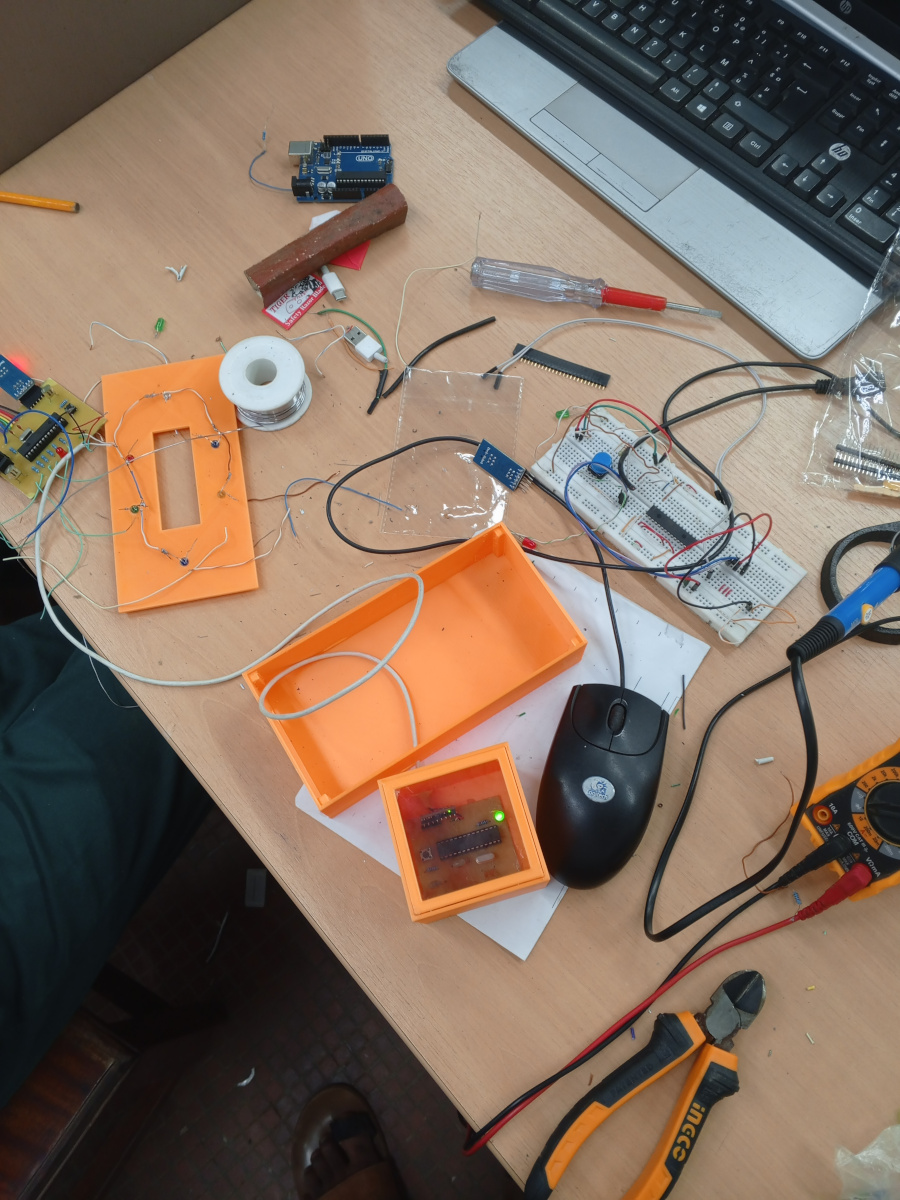 | 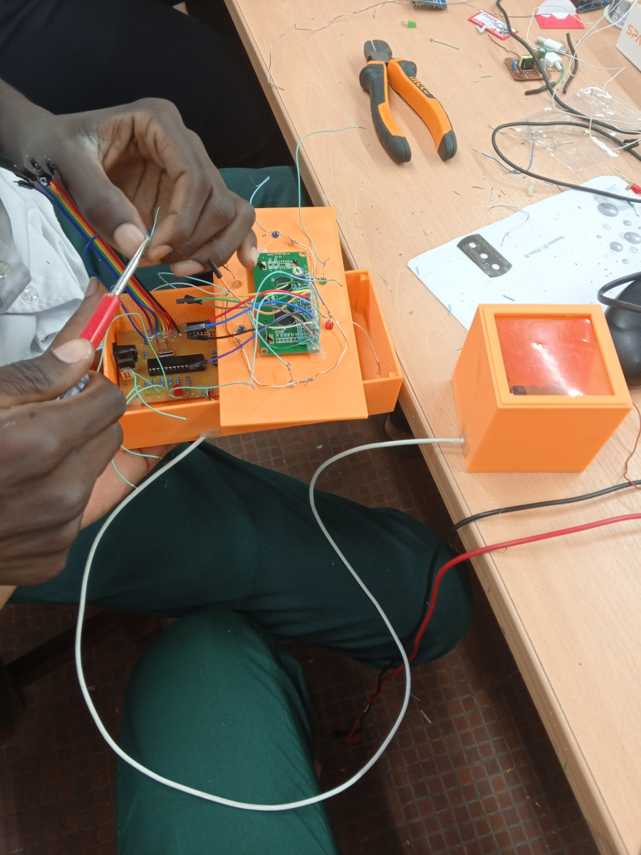 |  |
 |  |  |
 |  |  |
Videos
Resources and Useful Links
Provide links to resources, tutorials, and any other useful information that was referenced during the project.