Documentation: Assembly of the Mechanical Gripper
Short Demo
---Link to Download: Link to download
Introduction
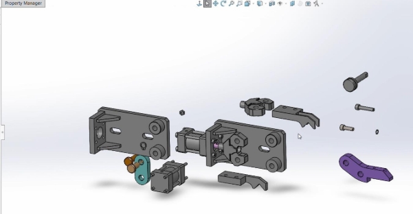
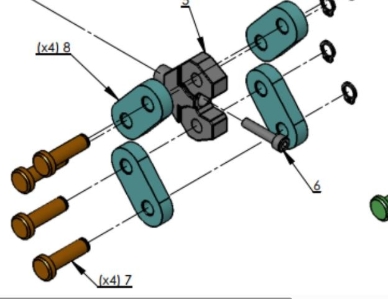
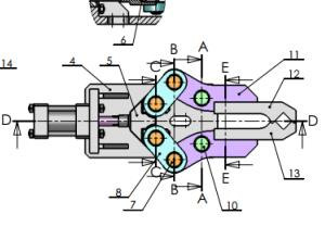
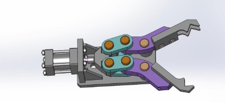
The challenge is to assemble a mechanical gripper based on precise assembly plans while respecting dimensions and geometric constraints. The assembly consists of several separate parts, each playing a specific role in the overall operation of the gripper. These parts include:
Key Components
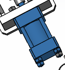
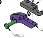
Jack: The main actuator that allows the gripper to open and close.
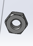
M4 Nut: Mechanically holds the elements together.
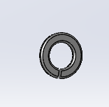
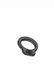
W4 circlips: Distributes the pressure of the screws to prevent damage to the surfaces.
Body: The main structure of the gripper, serving as support for all other parts.
Jack End: Connector between the Jack and the links.
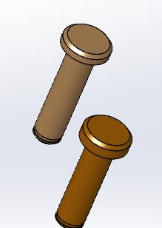
M5x25 Socket Head Screw: Provides a solid fixation of the elements, particularly to secure the Jack end.

Link Pin and Jaw Holder: Allows the rotation of the links and jaw holders.
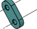
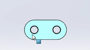
Link: Transmits the movement from the Jack to the jaws.
Circlip: Axially holds the pins to prevent misalignment.
Jaws: The movable parts of the gripper, responsible for grasping objects.
Note: All parts are available in the provided ZIP file. Make sure to import them into SolidWorks before starting.
These can be found in the various files after decompressing the zip file.
Assembly Steps
1. Open the parts in SolidWorks
To begin the assembly, it is necessary to open the files in SolidWorks. Once the interface is launched, click on the "Open" icon and select the file “Gripper Assembly”.

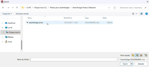
This file is already configured as an assembly (.sldasm), which means there is no need to create a new assembly manually. The Jack is already fixed to the body, but the other necessary components still need to be added.
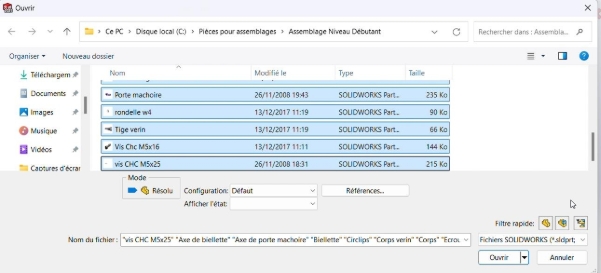
For this, use the "Insert Components" option in the top toolbar, then select the available parts from the decompressed folder.
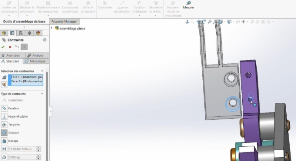
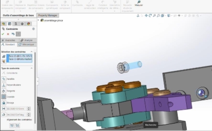
Geometric constraints, such as coaxiality and coincidence, will be essential for correctly aligning the elements. For example, to align two cylindrical surfaces, apply a coaxiality constraint, then use a coincidence constraint to fix the contacting faces.
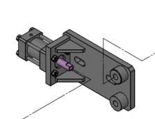
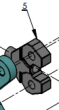
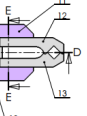
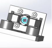
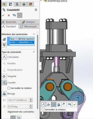
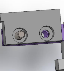
Fixing the Jack
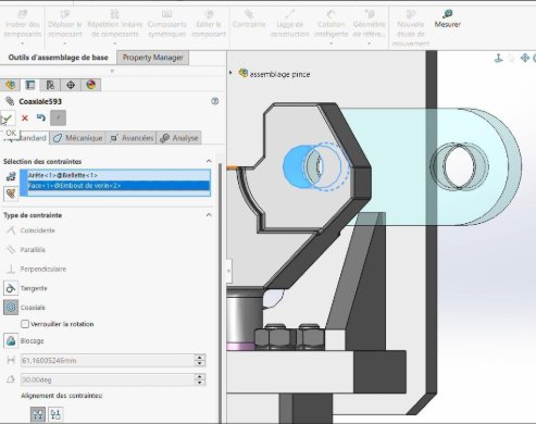
Fixing the Jack is a crucial step, as it ensures that the movement transmitted by the Jack will be correctly relayed to the other components. In the diagram, it can be seen that the rod of the Jack is connected to the end piece via an M5x25 socket head screw. To make this connection, start by aligning the axis of the screw with the cylindrical cavities of the end piece and the Jack rod.
Methodology:
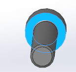
Select the Constraint tab
Select coaxiality and then click on the cylindrical faces of the cavity and the screw.
Select the coincidence constraint between the base face of the screw cap and the first drilled surface of the cavity.
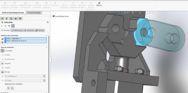
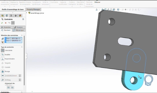
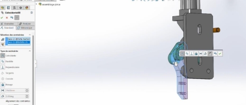
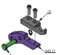
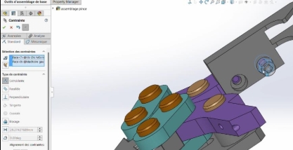
Assembly of the Links
The links play a central role in transmitting the movement from the Jack to the jaws. Each end of the Jack is connected to a pair of links, forming a sandwich-like configuration. The links are held in place by the link pins and circlips, which prevent any dislocation of the assembly.
Steps:
Fix one link on one of the axial ends of the Jack end.
Apply a coaxiality constraint between the extreme axial cavities of the link and the end piece.
Apply a coincidence constraint between the opposite faces of the link and the end piece.
Secure the assembly with the pins and circlips.
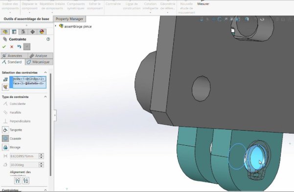
Repeat the process for the second end of the Jack.
Apply a parallelism constraint between the opposite faces of the links.
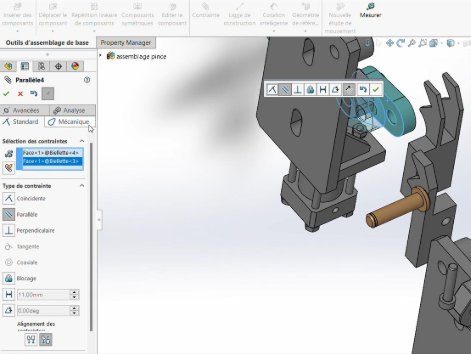
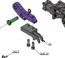
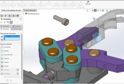
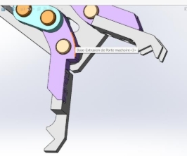
Mounting the Jaw Holders
The jaw holders consist of two rotation axes: let's name them A1, located at the rounded end, and A2, located at the elongated end. Axis A1 is directly fixed between the links via their pins, while A2 is fixed to the main body via jaw holder pins and circlips.
Steps:
Align A1 and A2 on the same axis as their respective cavities.
Apply a coincidence constraint between A1 and one of the faces of the links.
Secure the pins and circlips.
Mounting the Jaws
The jaws are fixed on the truncated face of the jaw holders at the elongated end and are held in place by two pins to ensure strength and durability.
Steps:
Apply a coincidence constraint between the contact surfaces of the jaws and the jaw holders.
Use a coaxiality constraint to align the cylindrical cavities of the jaws with the corresponding pins.
Secure each cavity with M5x16 socket head screws.
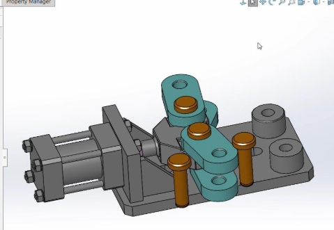
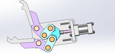
Final Assembly
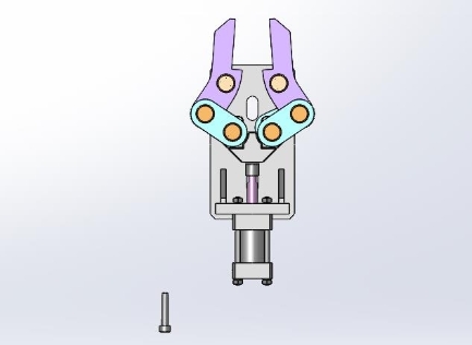
In the end, we obtain the sketch of a mechanical gripper capable of grasping and releasing objects.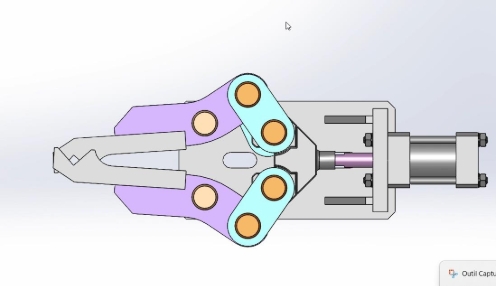
Additional Tips
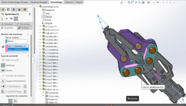
Application of the Symmetry Constraint
To ensure synchronized movement of the links or jaw holders, apply a symmetry constraint between the opposite faces of the links.
Select the Symmetry constraint under the advanced options.
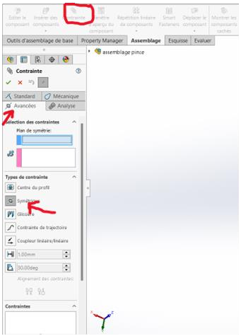
Select the top plane as the axis of symmetry.
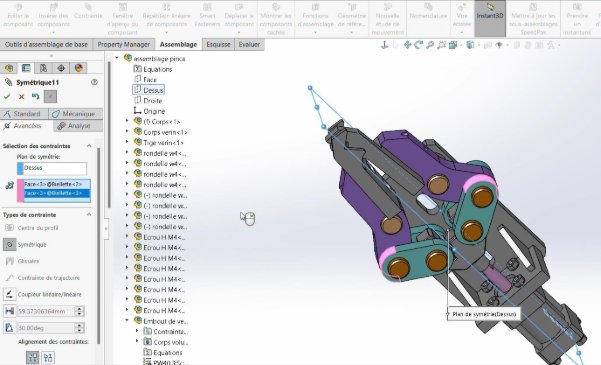
Apply the constraint between the opposite faces.
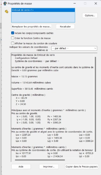
Determining the Center of Gravity
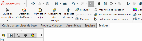
To determine the center of gravity, go to the Evaluate tab at the top left and select the Mass Properties option.
The coordinates of the center of gravity are:
- (X = -30.29, Y = 0.0, Z = 24.50) at its maximum position.
- (X = -45.29, Y = 0.00, Z = 24.50) at its minimum position.
Errors to Avoid During Assembly
Incorrect orientation of parts can lead to unexpected effects.
Confusion of screws.
Ensure that you have used all the parts.