Documentation for Advanced Mechanical Design Challenge
Challenge Overview
The Tekbot Robotics Challenge 2025 (TRC2K25) is a rigorous competition designed to evaluate the technical skills of participating teams across multiple disciplines: Electronics, IT, and Mechanics. Over the course of five weeks, teams will face weekly challenges that test their expertise in these domains. Each challenge builds upon the previous one, culminating in a final multidisciplinary project where all sub-teams must collaborate to solve a complex problem.
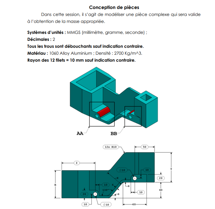
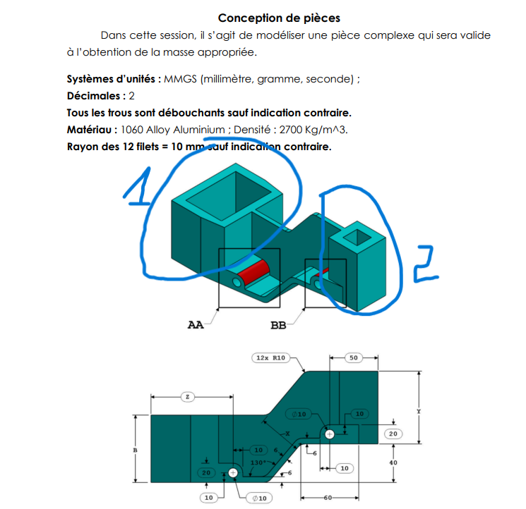
This documentation focuses on the Mechanical Design Challenge, specifically the advanced level, which requires participants to design and model a complex mechanical part using SolidWorks. The objective is to create a functional and precise 3D model, calculate its mass for various configurations, and ensure compliance with specified dimensions and constraints.
Link to Download: Link to download
Implementation Steps
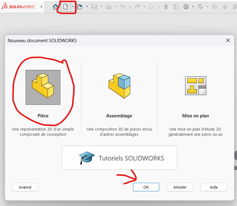
Step 1: Opening SolidWorks and Setting Up Global Variables
To begin, open SolidWorks in Part Mode. This step is crucial as it sets the foundation for the entire design process.
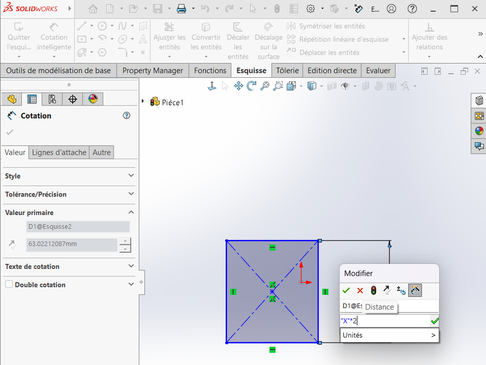
Define Global Variables
Most dimensions in this design depend on global variables, which can significantly impact the geometry and, consequently, the final mass. To define these variables:
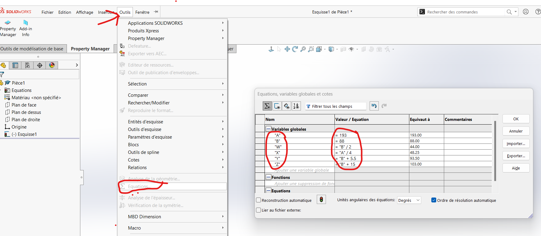
Navigate to
Tools > Equations.In the table that appears, insert the required variables and assign them initial values based on the problem statement.
- Example Variables:
A,B,W,X,Y,Z.
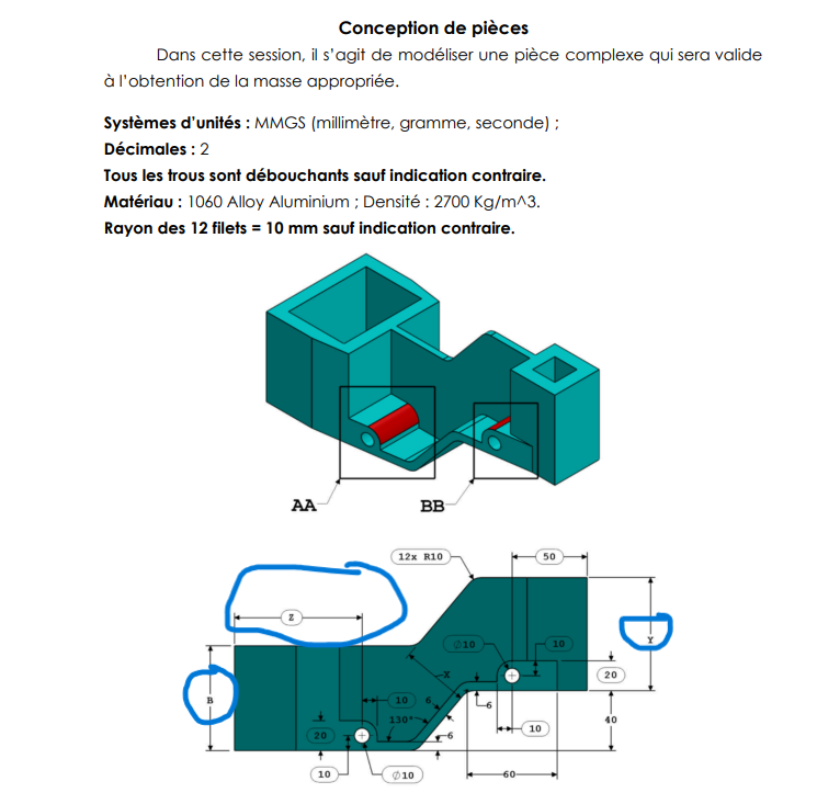
- Assign default values for the first configuration:
A = 193 mmB = 88 mmW = B/2 mmX = A/4 mmY = B + 5.5 mmZ = B + 15 mm
- Example Variables:
Detailed Explanation: Using global variables ensures that all dimensions are dynamically linked. This means that when you update a variable (e.g., changing
Afrom 193 mm to 205 mm), the entire model updates automatically. This approach not only saves time but also minimizes errors during iterative design processes.
Step 2: Creating the Prismatic Sections
The design begins with the creation of prismatic sections, which serve as the foundational structure of the part. These sections are modeled as primitive shapes, such as cubes and rectangular prisms, before being refined into the final geometry.
Process
Select the Top Planefrom the left-hand sidebar.- Click on the
Rectangle Toolin the top toolbar under "Basic Modeling Tools."
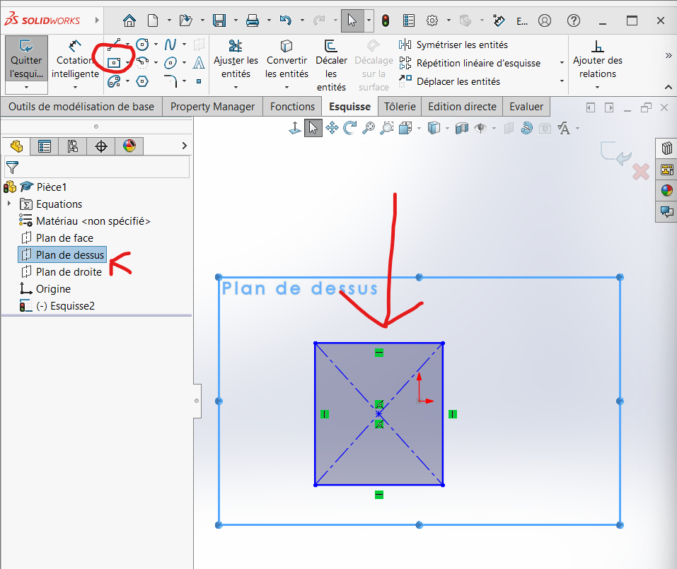
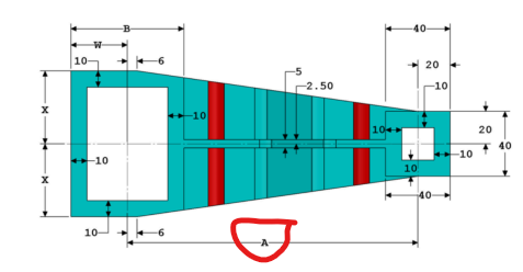
- Draw a rectangle and apply the following dimensions:
- Height:
2 * X - Width:
B
- Height:
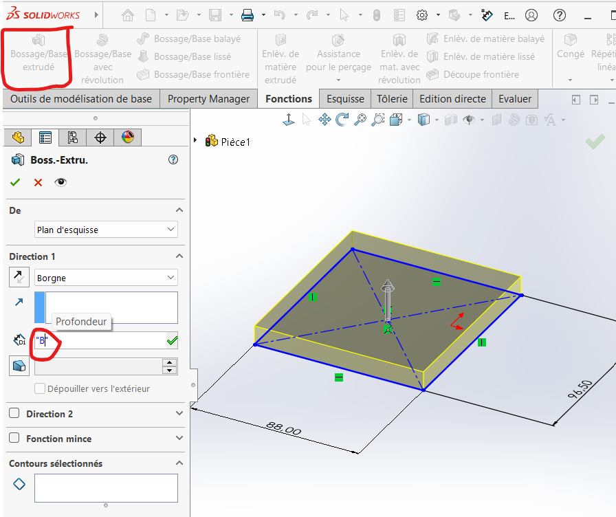
- Extrude the rectangle by
Bmm:- Go to
Features > Extruded Boss/Base. - Set the height to
B.
- Go to
- Draw a construction line horizontally to serve as a reference for the second prism.
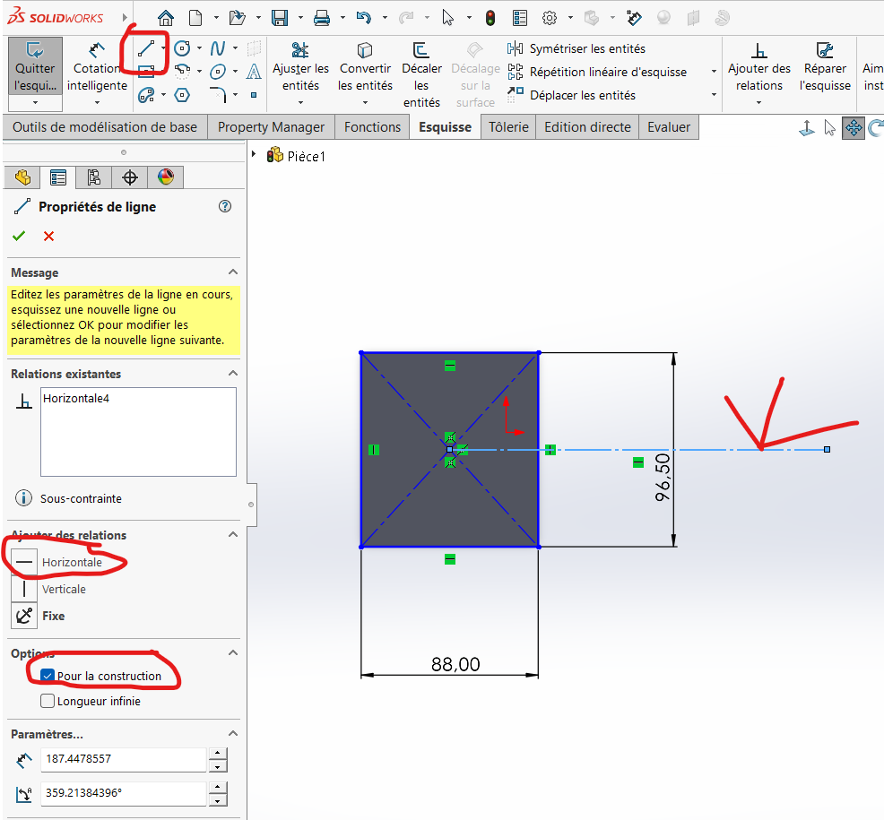
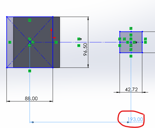
Draw a square starting from this line and dimension it to
40 mm.Apply a distance of
Amm between the two rectangles.
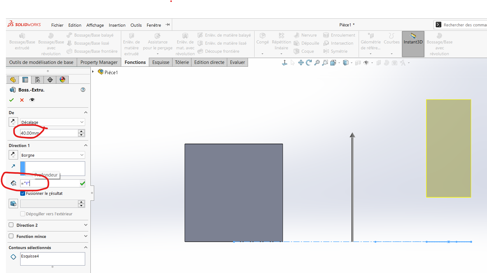
- Extrude the square by
Ymm with an offset of40 mmfrom the sketch plane.

Detailed Explanation: The use of construction lines and precise dimensioning ensures that the prismatic sections are aligned correctly. This alignment is critical for maintaining symmetry and balance in the final design.
Step 3: Adding the Chamfer-Like Inclination
The design includes a slight chamfer-like inclination between the two prisms. This feature adds complexity to the model and tests the participant's ability to handle intricate geometries.
Process
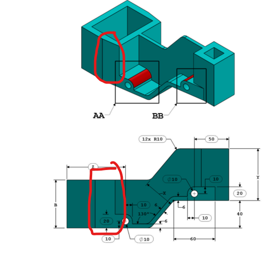
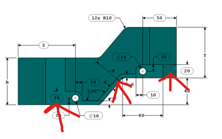
- Analyze the top view to identify the key points:
- The endpoints of the horizontal median of the small square.
- Points located
6 mmfrom the horizontal median of the large rectangle.
- Draw a construction line connecting these points.
- Extrude the excess material using the "Select All" option and orient the direction correctly.
- Apply symmetry to replicate the inclination on the opposite face.
Workshop
Detailed Explanation: The chamfer-like inclination demonstrates the participant's ability to manipulate geometric relationships. By carefully aligning the construction lines and applying symmetry constraints, the design achieves both aesthetic appeal and functional precision.
Step 4: Connecting the Two Prisms
Next, we will create a base structure to connect the two prismatic sections. This step involves designing a bridge-like feature that ensures structural integrity while maintaining the overall symmetry of the part.
Process
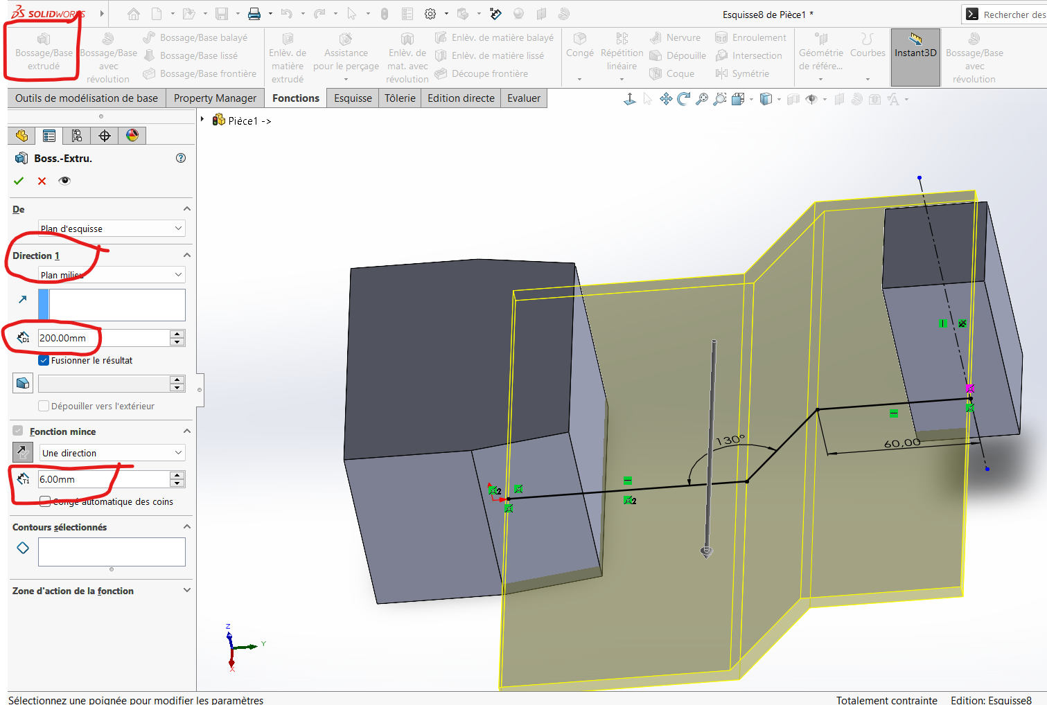
- Draw three broken lines approximating the shape of the base connection.
- Apply the required dimensions to ensure accuracy.
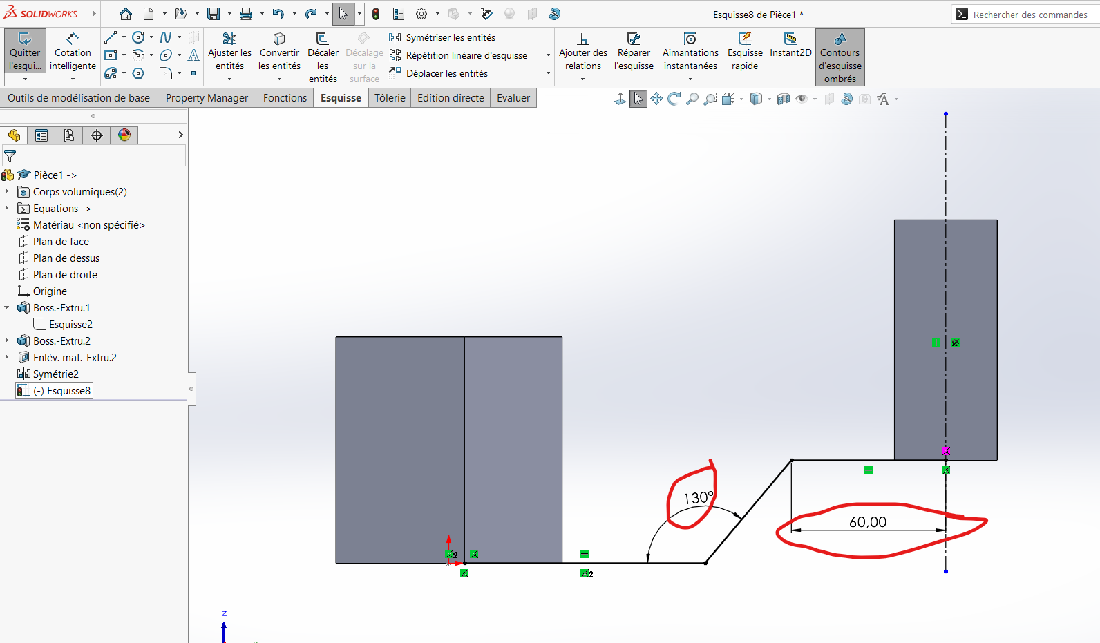
- Extrude the sketch: Use a middle plane with a depth of
200 mmand a thickness of6 mm. This approach minimizes errors by allowing us to refine the extrusion later.
- Select the necessary portion of the generated surface.
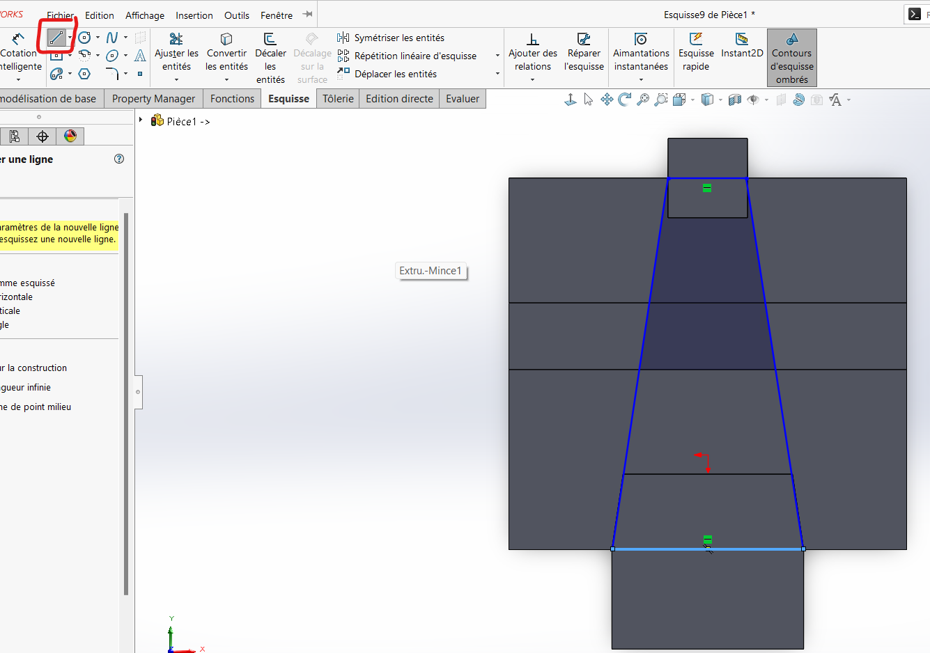
- Extrude the selected area using Boss/Base Extrude.
- Use the
Combine Featureto retain only the intersection between the new extrusion and the previously generated surface.
Workshop
Detailed Explanation: The base connection serves as a critical link between the two prisms. By carefully selecting and refining the extruded surfaces, we ensure that the final design is both structurally sound and visually appealing.
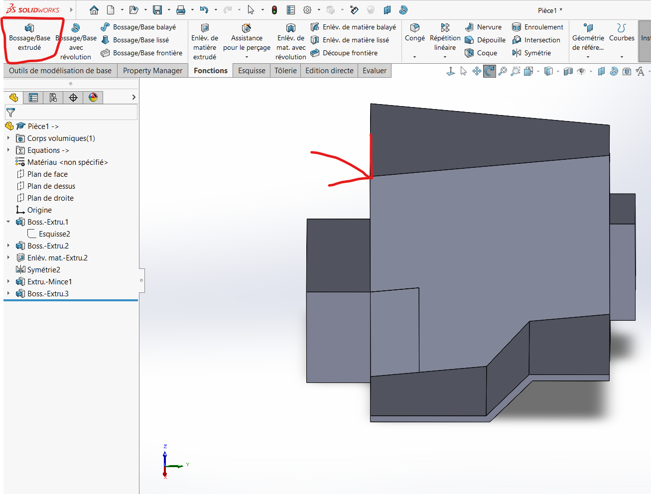
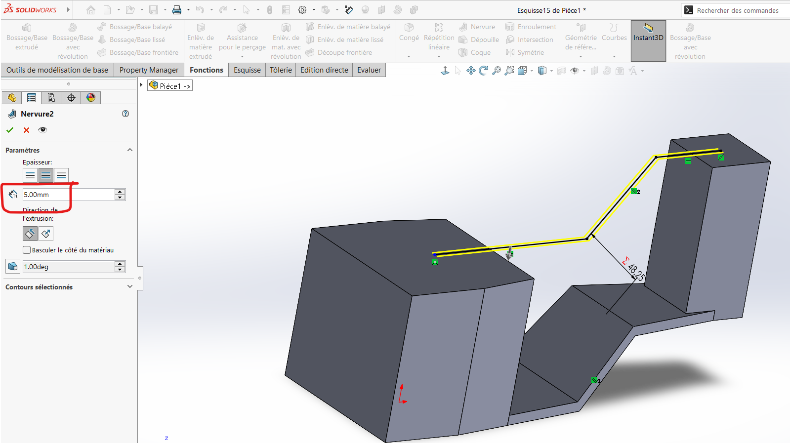
Step 5: Building the Vertical Wall
The vertical wall is an essential component of the design, providing additional structural support and housing features such as mounting points or attachment mechanisms.
Process
- Draw the upper border of the wall using lines, ensuring it is parallel to the base.
- Use the
Rib Featureto create a spatial configuration with a thickness of5 mm.
- Apply fillets (
R = 10 mm) to all relevant edges.
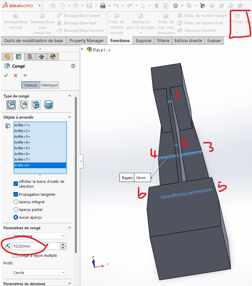
Detailed Explanation: The vertical wall demonstrates the participant's ability to integrate multiple features into a single design. By combining ribs, fillets, and precise dimensioning, the wall achieves both functionality and aesthetic appeal.
workshop
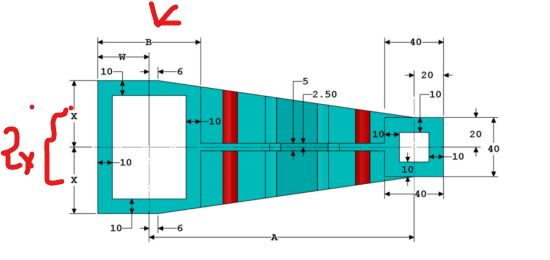
Step 6: Creating Rectangular Cavities at the Ends
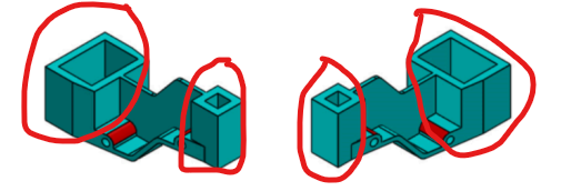
The design includes rectangular cavities at the ends of the prismatic sections. These cavities reduce the overall weight of the part while maintaining structural integrity.
Process
- Draw rectangles centered on the faces of each prism.
- Extrude-cut the rectangles through the entire height of the prisms.
workshop
Detailed Explanation: The cavities are strategically placed to optimize the part's weight-to-strength ratio. By carefully dimensioning and positioning these features, the design achieves a balance between performance and efficiency.
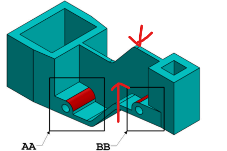
Step 7: Forming Features AA and BB
Features AA and BB are unique components of the design, requiring careful attention to detail and precise execution.
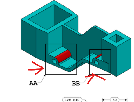
Process
- Draw a rectangle with the specified dimensions.
- Extrude it symmetrically across the wall for uniformity.
- Apply a fillet (
R = 10 mm) to the contoured edge. - Draw a circle (
D = 10 mm) centered on the fillet and perform a cut-extrude through the entire structure.
Workshop
Detailed Explanation: Features AA and BB showcase the participant's ability to integrate complex geometries into the design. By combining extrusions, fillets, and cut-outs, these features demonstrate both creativity and technical proficiency.
Step 8: Assigning Material
Assign the material Aluminum Alloy 1060 to the part:
- Go to
Material > Edit Material. - Select
Aluminum Alloy 1060from the list and confirm.
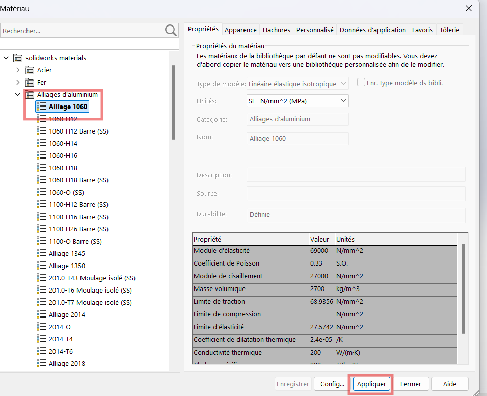
Detailed Explanation: Material selection is a critical step in the design process. Aluminum Alloy 1060 was chosen for its lightweight properties and excellent strength-to-weight ratio, making it ideal for this application.
Step 9: Determining the Mass
Finally, calculate the mass of the part for the given tuples of variable values:
- Ensure the correct values are assigned to the global variables.
- Go to
Evaluate > Mass Properties.
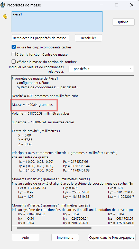
Results:
- For
(A, B, W, X, Y, Z) = (193, 88, B/2, A/4, B+5.5, B+15)→ Mass = 1400.64 g - For
(A, B, W, X, Y, Z) = (205, 100, B/2, A/4, B+5.5, B+15)→ Mass = 1651.40 g - For
(A, B, W, X, Y, Z) = (210, 105, B/2, A/4, B+5.5, B+15)→ Mass = 1760.41 g
Detailed Explanation: The mass calculation is a key metric for evaluating the success of the design. By iterating through different configurations and comparing the results, participants can assess the impact of each variable on the final design.
Additional Notes
- Always double-check dimensions and constraints before proceeding to extrusion.
- Use construction lines and geometric relations (e.g., symmetry, coincidence) to maintain precision.
- Regularly save intermediate versions of your file after major steps.