Documentation for Part 2 of Week 2
Challenge Overview
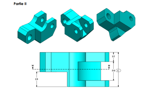
The objective of this exercise is to modify the piece created in Part 1 (link to Part 1) by applying precise material removal at strategic points while respecting dimensions, tangency constraints, and other specifications.
Short Demo
Link to Download: Link to download
Implementation Steps
Step 1: Second Cylindrical Drilling
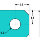
We will begin by performing an 11 mm diameter drilling on both ends of the piece at the second extremity.
Process
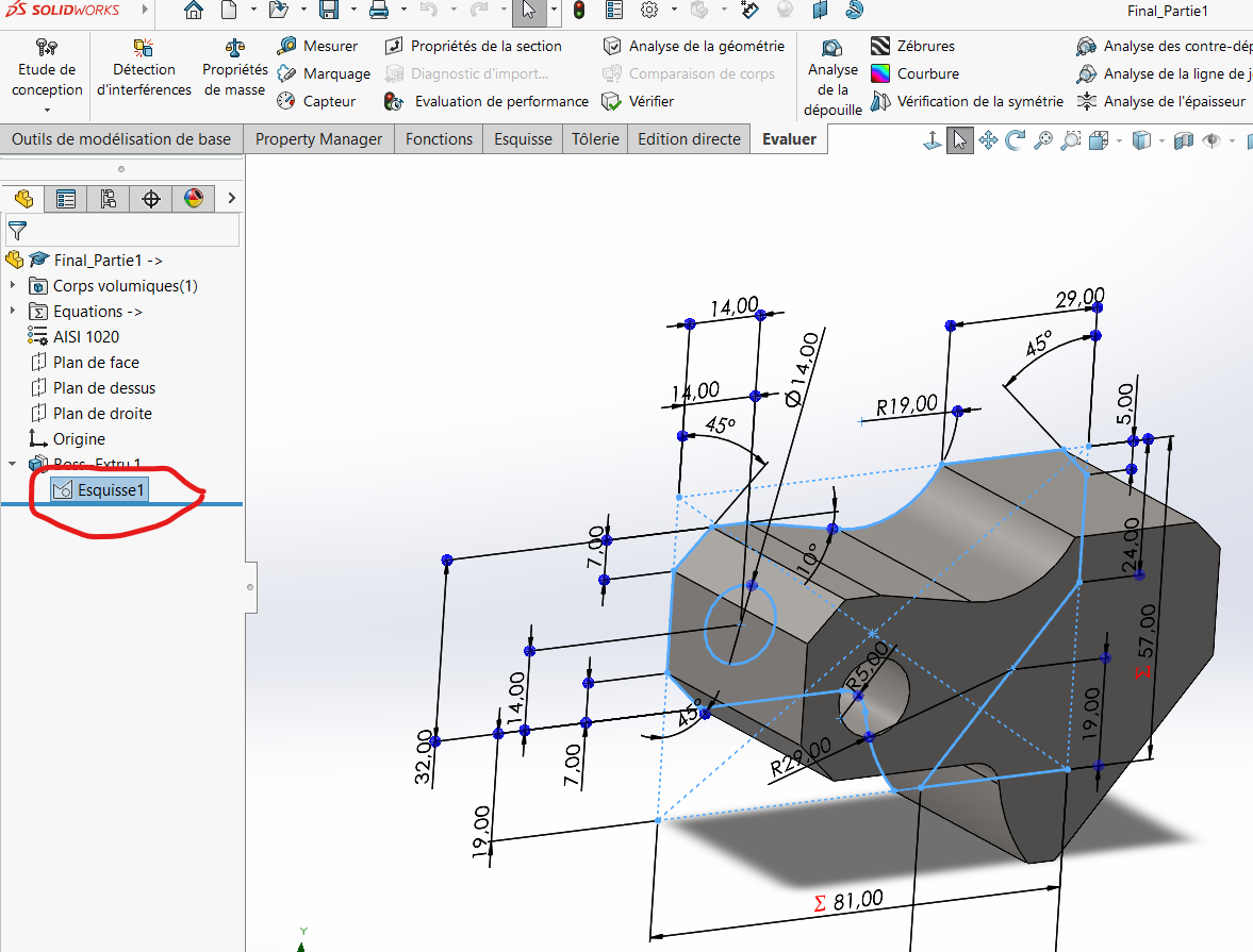
Select the base sketch for the operation.
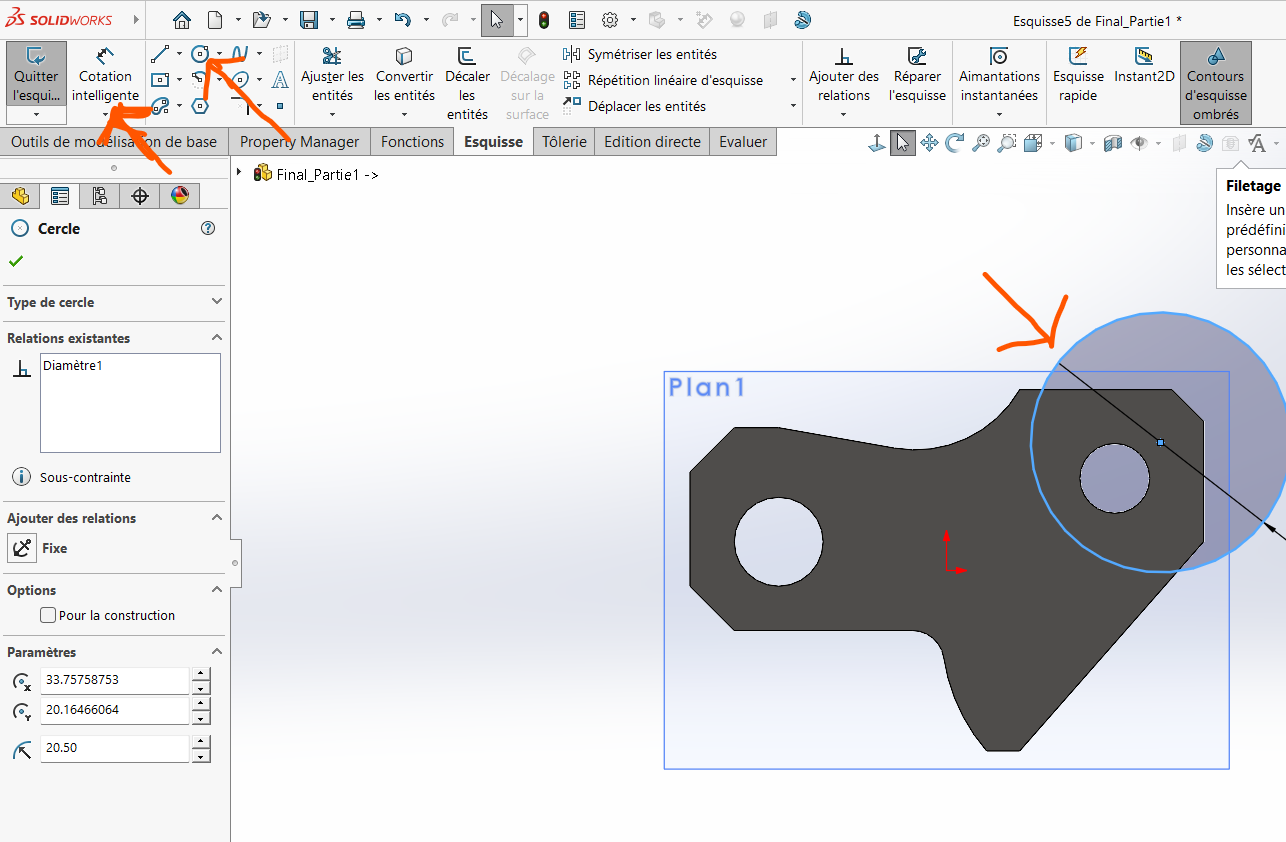
Draw a circle at the desired extremity and apply the correct dimensions.
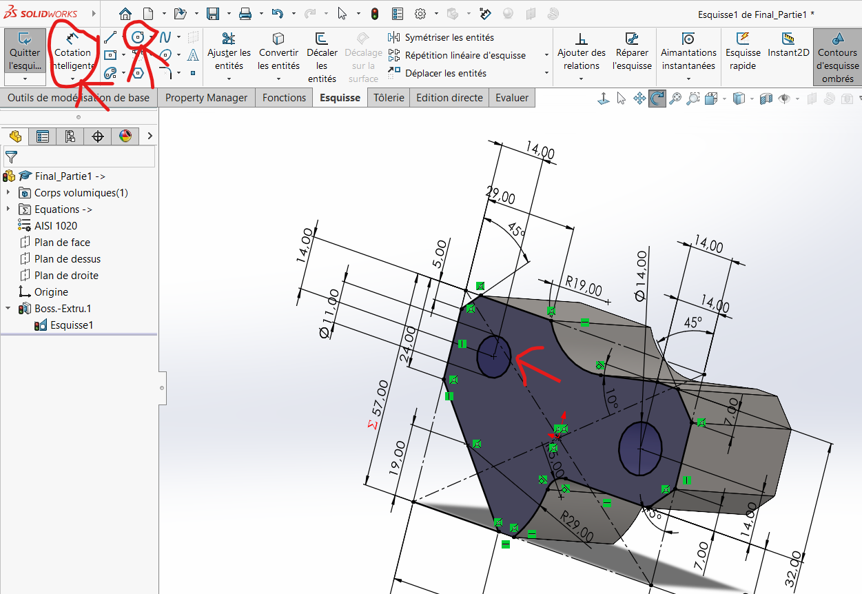
Apply material removal using the drawn circle:
- Click on
Features > Extrude/Cut Material. - Select the circle and apply the extrusion.
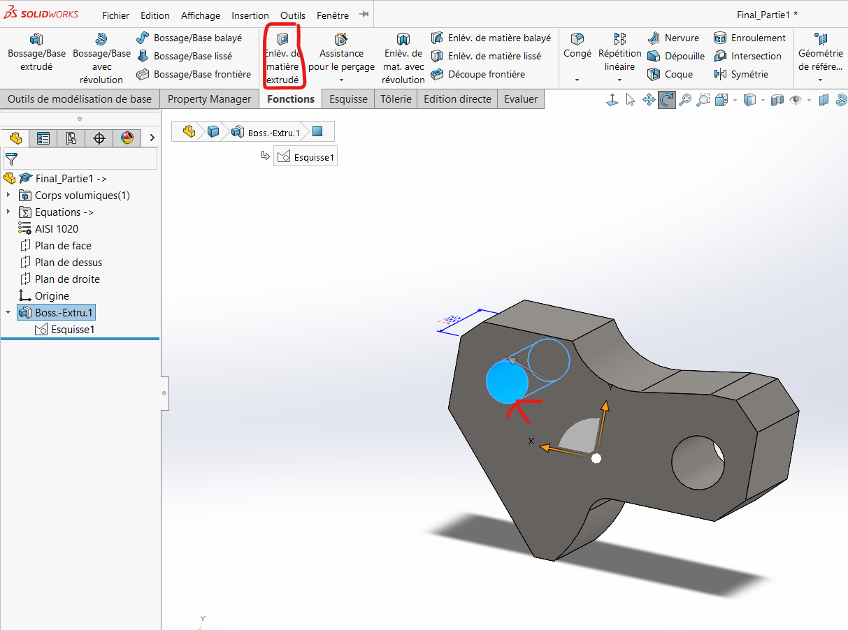
- Click on
Note: The software defaults to "up to the next surface," but you can also adjust it manually if needed.
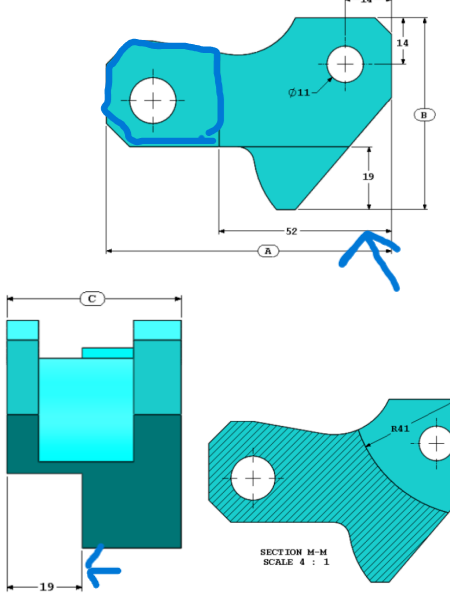
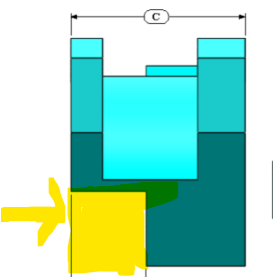
Step 2: Create a Prismatic Cut
Process
Divide the piece into three sections as shown below:
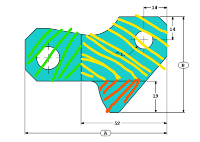
To achieve this:
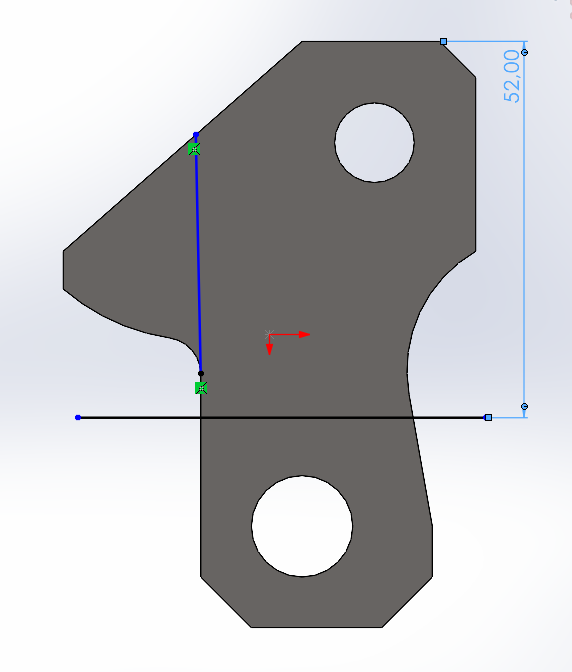
Draw a horizontal line and dimension it at 52 mm from the opposite extremity.
Draw a second horizontal line to delimit the crest.
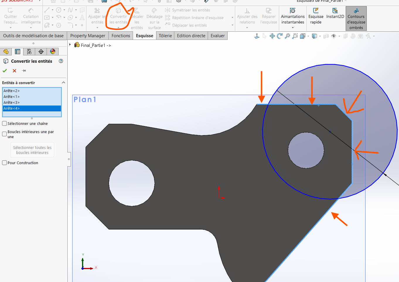
Use the
Convert Entitiestool to select the contours of the surfaces to be extruded.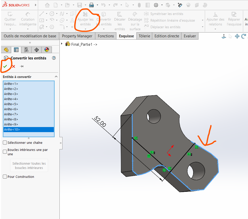
Use the
Trim Entitiestool to remove excess outlines.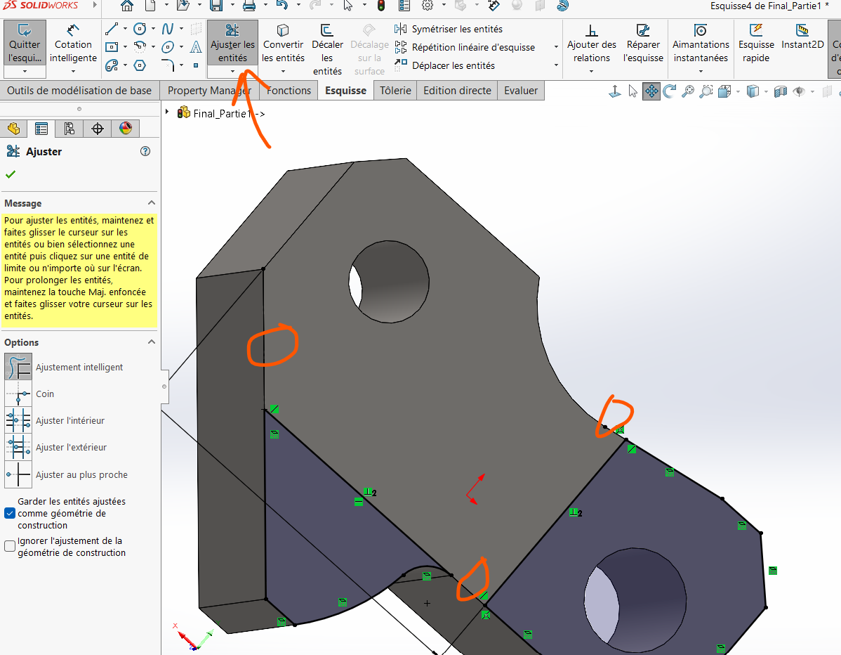
Perform an extrusion of 19 mm on these surfaces.
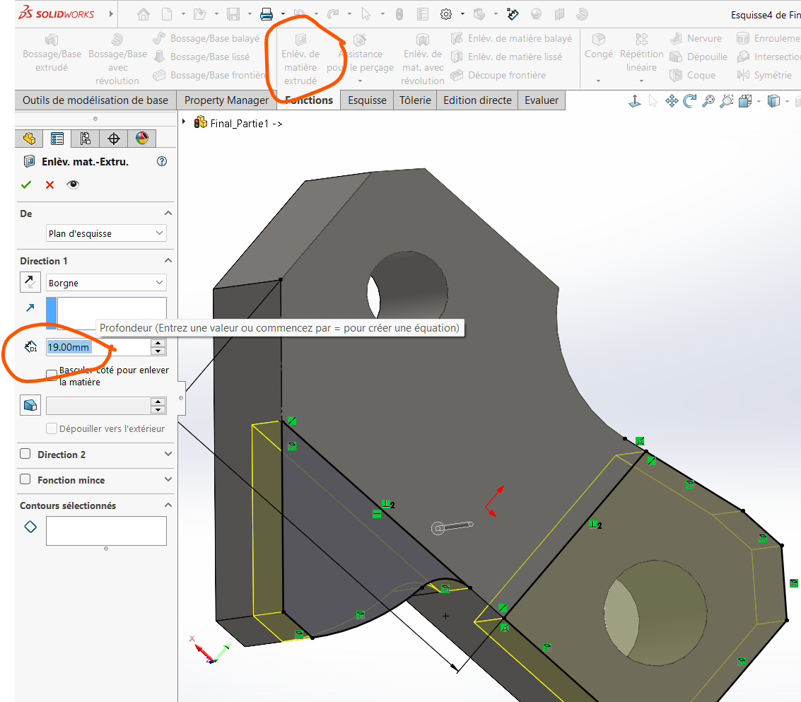
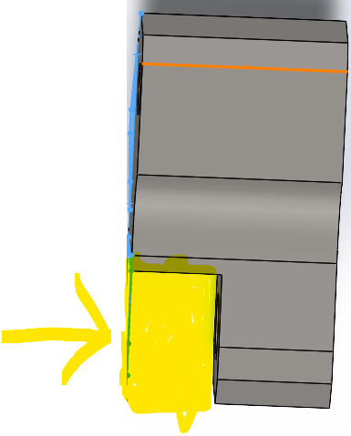
Warning: Always ensure the correct face orientation for the sketch. The extrusion zone is on the left when the crest faces forward.
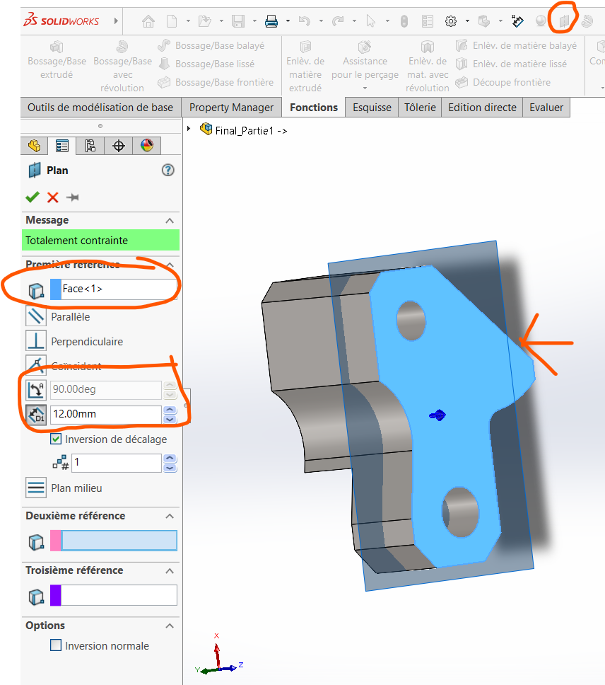
Step 3: Create the Last Semi-Cylindrical Cavity
We will now focus on the final drilling step.
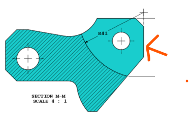
Process
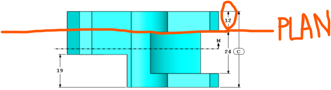
Create a plane located 12 mm from the solid face of the piece.
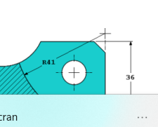
Draw a circle in the area to be drilled and dimension its radius to 41 mm.
Apply a dimension of 36 mm.
Delimit an entity in the specified zone:
- Click on
Convert Entitiesand select the area to be delimited.
- Click on
Use the
Trim Entitiestool to polish and remove excess portions.
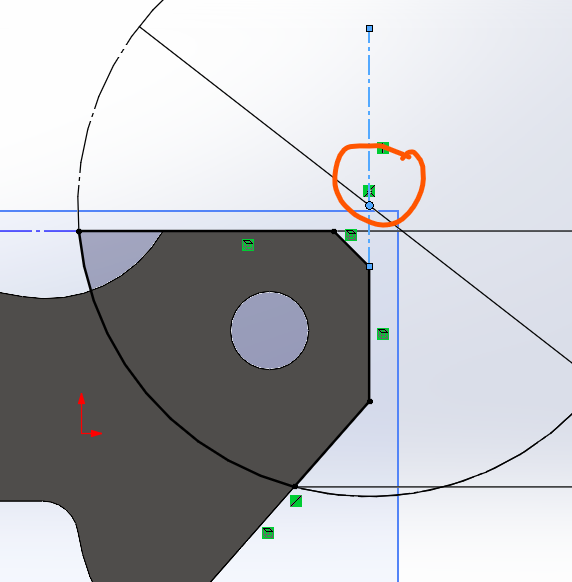
Align the center of the circle with the extreme edge:
Draw a vertical construction line along the extreme edge.
Apply a coincidence relation between the circle's center and the line.
Apply a material removal of 24 mm from the obtained surface:
- Click on
Extrude/Cut Material. - Select the opposite side of the solid face and input the value
24mmin the dimension field.
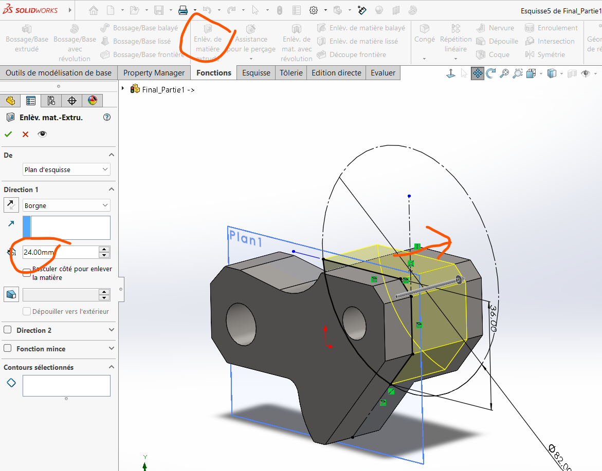
- Click on
Step 4: Determine the Mass
To calculate the mass of the piece:
Select Equation icon and actuate the values of global variables
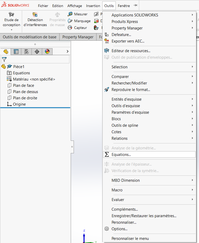
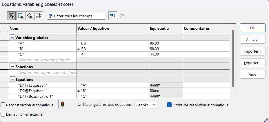
Click on the
Evaluatetab, then selectMass Properties.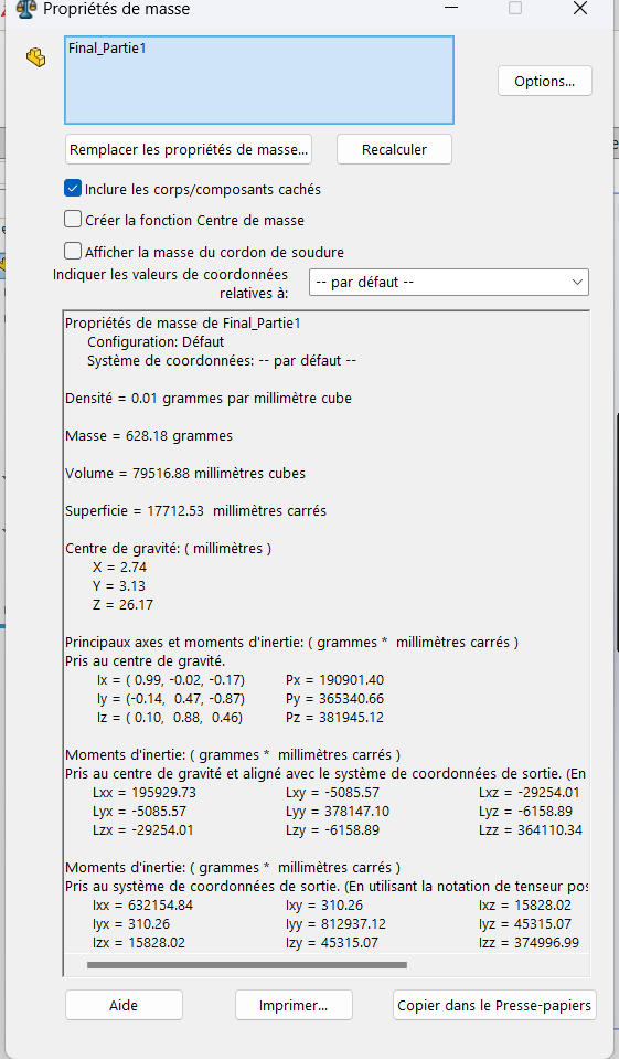
The final mass obtained for this test is 628.18 g.
Additional Notes
Always double-check dimensions and constraints before applying material removal.
Ensure proper alignment of features to avoid misplacement during extrusion.
Use construction lines and geometric relations (e.g., coincidence, tangency) to maintain precision.