Documentation of Piece IV Modeling for TRC 2025 (Following Tutorial)
This document details the modeling process for Piece IV.
Short Demo
Link to Download: Link to download
Preliminary studies
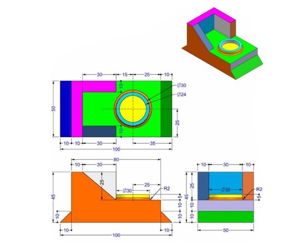
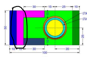
Analyzing functional needs and mechanical constraints based on the technical drawing.
Functional needs analysis
Piece IV requires a robust structure with precise dimensions for robotic assembly, using Aluminum Alloy 1060.
Mechanical constraints
- Dimensions in MMS (millimeter, gramme, seconde).
- Decimals to 2 places unless otherwise indicated.
- Material: Aluminum Alloy 1060, Density: 0.0027g.
Choice and Rationale
Aluminum Alloy 1060 is selected for its lightweight properties and strength, aligning with TRC’s emphasis on material efficiency.
CAD modeling
Modeling in SolidWorks based on the tutorial steps, adapted to Piece IV.
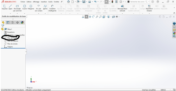
Step-by-Step Process
- New Part Creation: Start a new part file in SolidWorks.
![]()
![]()
![]()
- Sketch Creation:
![]()
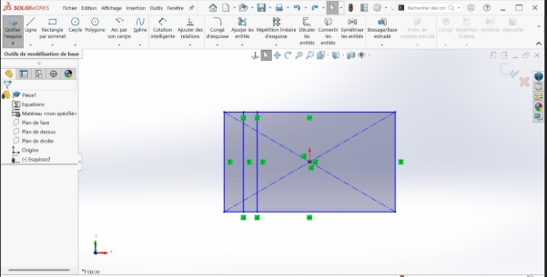
- Select the front plane:
- Use the “Rectangle” tool to draw the rectangle from the center:<
![]()
![]()
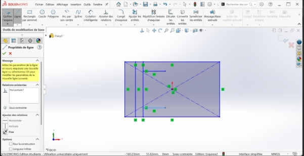
Still in the sketch, select line and draw two vertical bars separated by a small space on the left side:
![]()
-The part that we want to build:
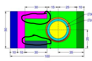
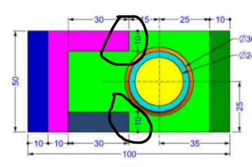
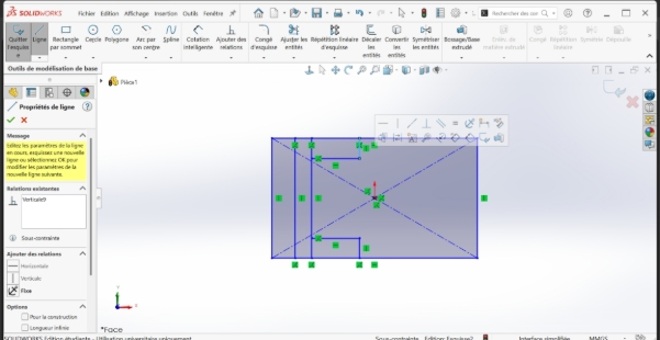
- Also in the sketch, select "line" and draw a horizontal bar at the top perpendicular to the last vertical line previously drawn
![]()
- Also in the sketch, select "line" and draw a horizontal bar at the bottom perpendicular to the last vertical line previously drawn and another at the top perpendicular to the same vertical line:
The part that we want to build:
- Still in the sketch, select "line" and draw a bar perpendicular to the bar perpendicular to the previous vertical and perpendicular to the lower length of the rectangle tracer
The part that we want to build:
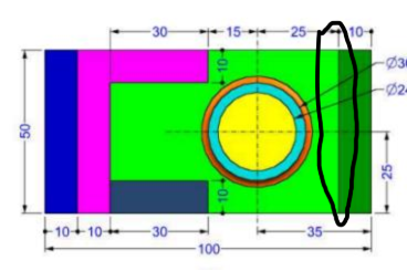
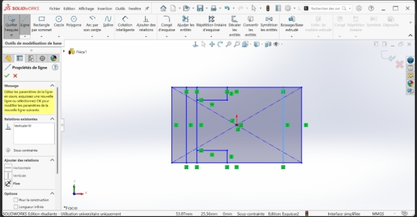
- Still in the sketch, select "line" and draw a vertical bar separated by a small space on the right side
The part that we want to build:
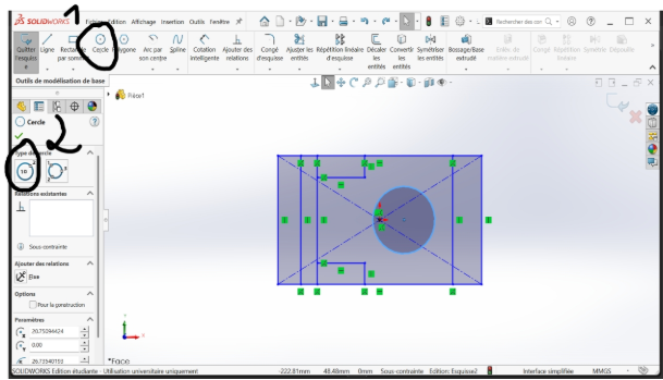
- select the circle option after leaving the line option and from the center, draw a circle that can stay in proportions.
The part that we want to build:
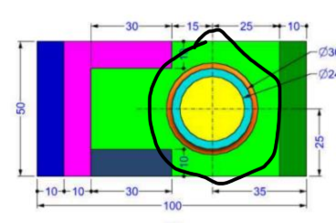
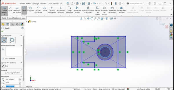
draw a circle within the circle previously drawn
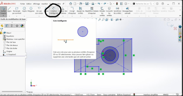
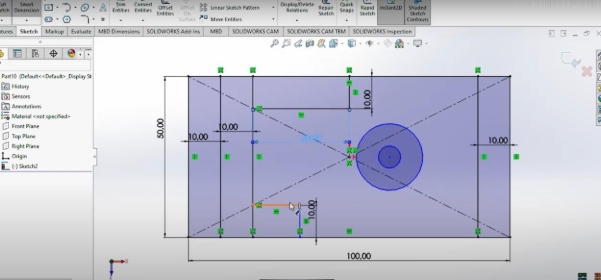
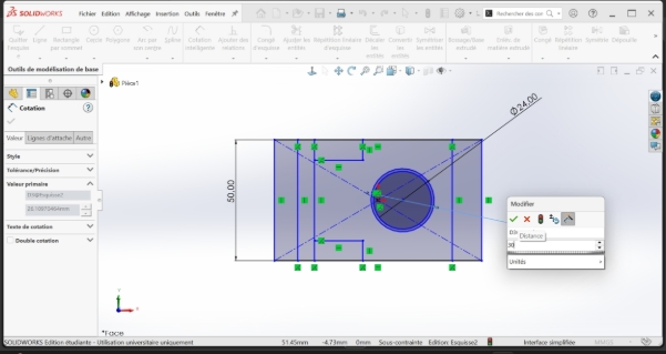
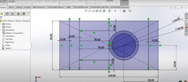
- Choose the smart dimenssion option. Click on the desired dimension after choosing smart dimession and drag to the desired dimension. After that, enter the desired dimension (the one written on the pdf). Do this for a better quality- it allows a conformation, an adaptation of the dimensions (do the same for all the other sides)
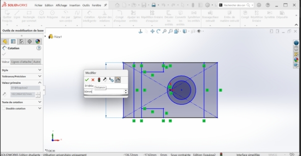
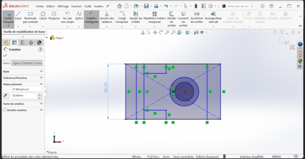
NB.: do it for all sides until you have this result
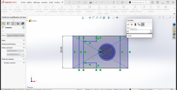
- For the circle, do the same but by drawing from the center and entering the dimension. Click on the edge of the circle whose dimensions you want to adjust (create a slope) and then drag to the side you want. Enter the date on the panel that is displayed without specifying time and validate
Here is the final result of the ribs
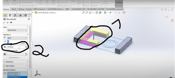
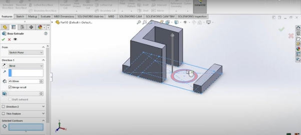
- Choose extrude and select the selected contours option and choose a region. Then, put the mouse on the part you want to extrude and click on it
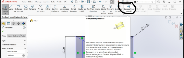
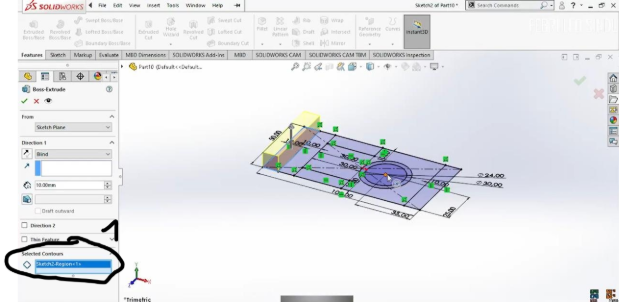
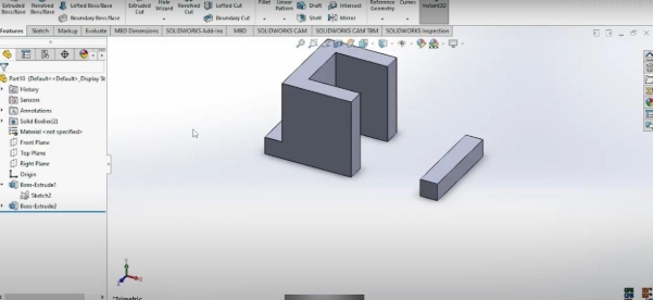
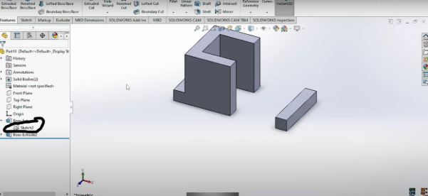
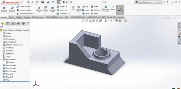
- do the same chos until you get this result
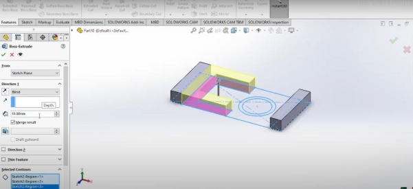
-for the highest part of the room, select the appropriate size and increase the height(45mm)
- for the circle, first click on the sketch to rev on your worktop and then click on the border of the larger circle after entering in extrude and bossage then put the size at 25mm and put that of sot at 20mm:
![]()
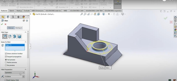
- In the sketch, click on the 'fillet' and then select the sides to model
![]()
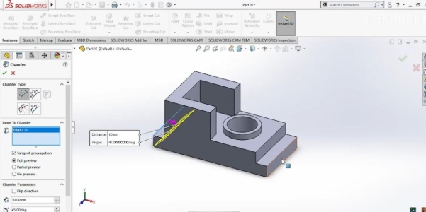
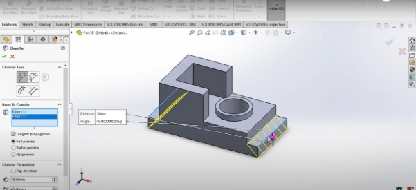
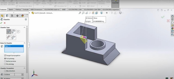
- Fillet and Chamfer: Add fillets (R2) to edges as per the drawing.
- Validation: Ensure all sketches are fully constrained and dimensions match the drawing
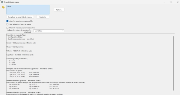
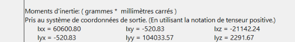
Calculation of mass
To determine the mass, this is the process:
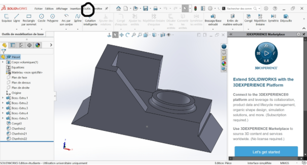
- go to the bar at the top and click on tools:
- after clicking on tools, go to the bottom of the strip that appears and click on the black arrow until the entire strip is scrolled
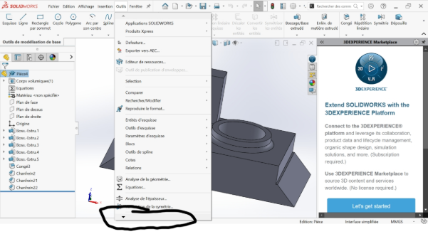
- click on evaluate and then on mass property:
- the result is as follows: