Documentation for Week 2 Assembly
Challenge Overview
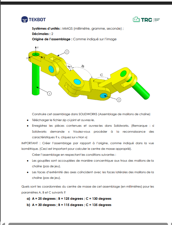
The objective of this exercise is to assemble a mechanical system using the provided parts while respecting the constraints and adhering to the origin of the assembly. The files required for this assembly can be downloaded via this lin. Once decompressed, you will have access to the necessary parts.
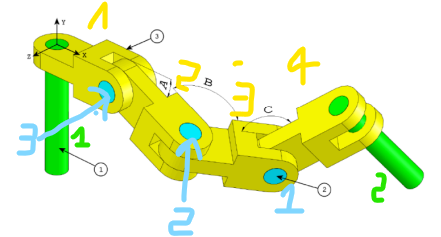
The goal is to apply different angle values (A, B, and C) at the rotational axes and determine the center of gravity (center of mass) for each configuration.
Short Demo
Link to Download: Link to download
Implementation Steps
Step 0: Opening and Importing Parts
Once the compressed file is extracted, open the parts in SolidWorks.
Process
Open
SolidWorks.Click on
New > Assembly.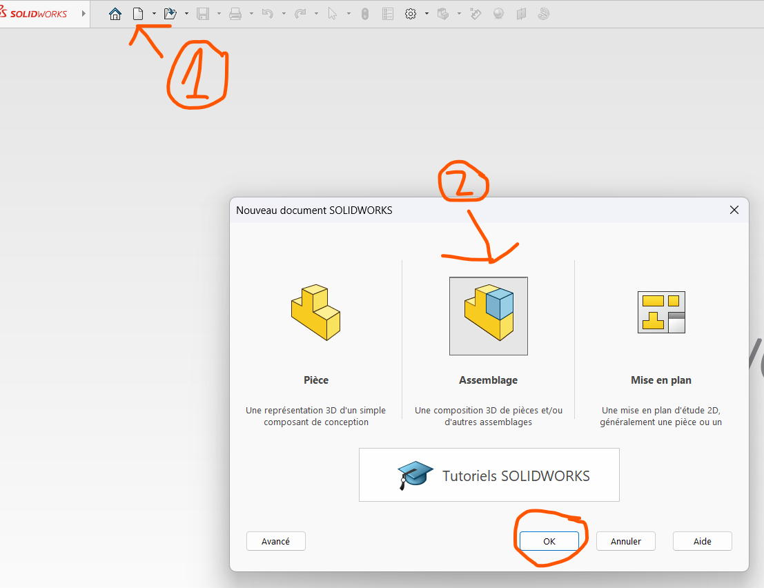
Select the file containing the parts and open it.
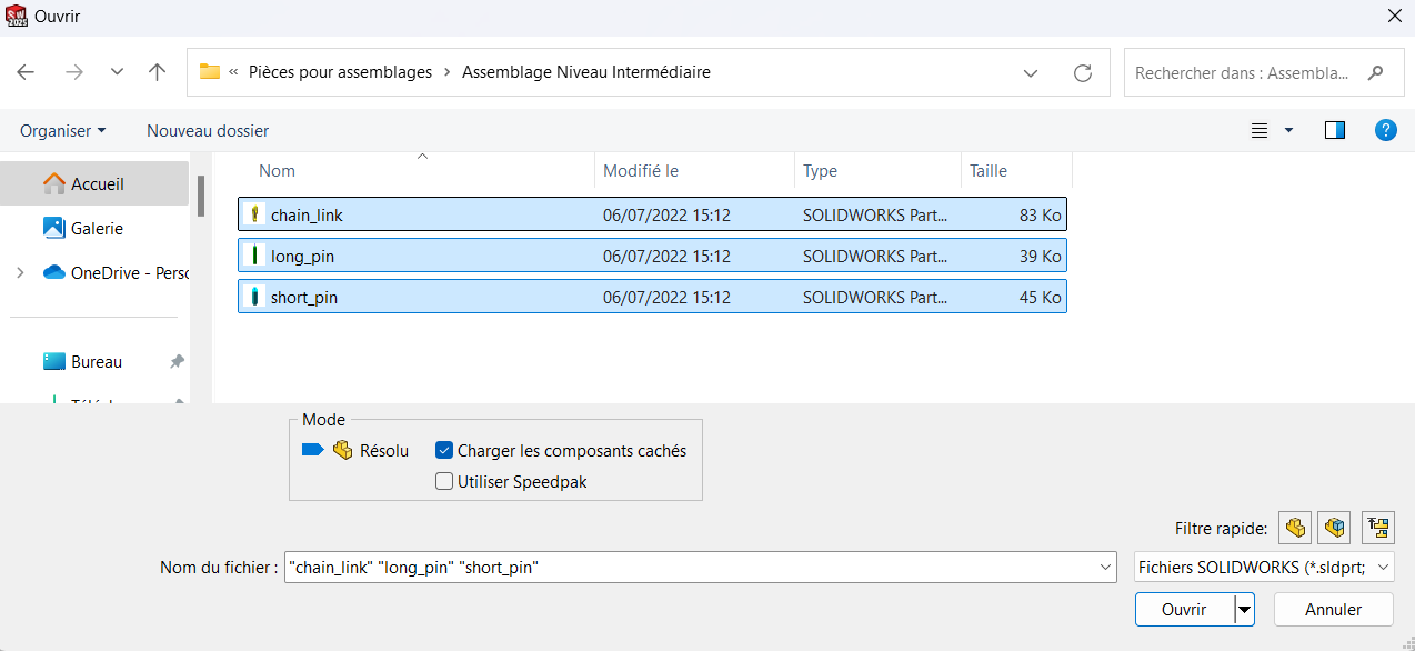
Uploaded
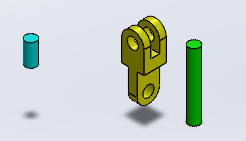
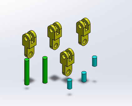
Duplicate the required pieces by copying (
Ctrl + C) and pasting (Ctrl + V).- Determine how many duplicates you need based on the assembly plan.
After duplication, ensure all required pieces are ready for assembly.
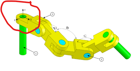
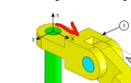
Step 1: Aligning the Base of a Long Pin with the Assembly Origin
This step is critical as the center of gravity will be determined relative to this reference point. The goal is to align the center of the base surface of a long pin with the origin of the assembly coordinate system.
Process
Select one of the pins and display its entities.
While holding
Shift, select both the origin of the part and the origin of the assembly.Apply a
Coincidence Constraintby clicking onAdd Mateand selecting the relevant faces.
Explanation: Proper alignment of the pin's base with the assembly origin ensures accurate calculations of the center of gravity later.
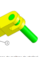
Step 2: Joining the Pin to the Connector
Here, we will attach a connector to the pin that was just fixed.
Process
Align the cylindrical cavity of the connector with the pin by applying a
Coaxiality Constraint.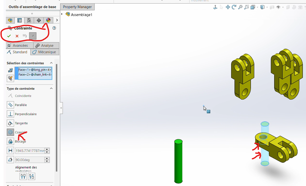
Apply a
Coincidence Constraintbetween the rear surface of the connector and the front surface of the pin.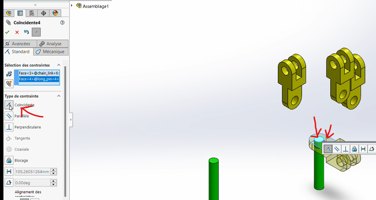
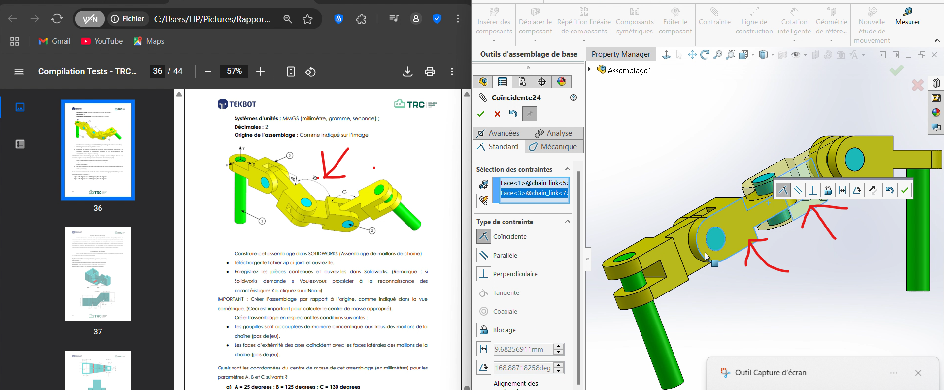
Step 3: Connecting Two Connectors
On the assembly plan, connectors are joined together via pins through their axes (front axis of connector 1 → rear axis of connector 2).
Process
- Apply a
Coaxiality Constraintbetween the cylindrical cavities of the two connectors' axes.
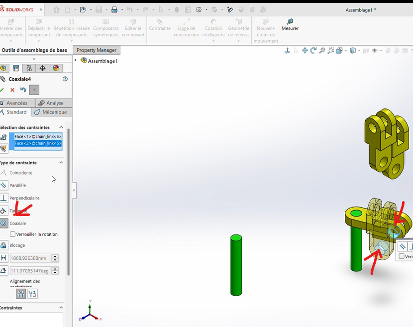
Apply a
Coincidence Constraintbetween the contact surfaces of the two connectors.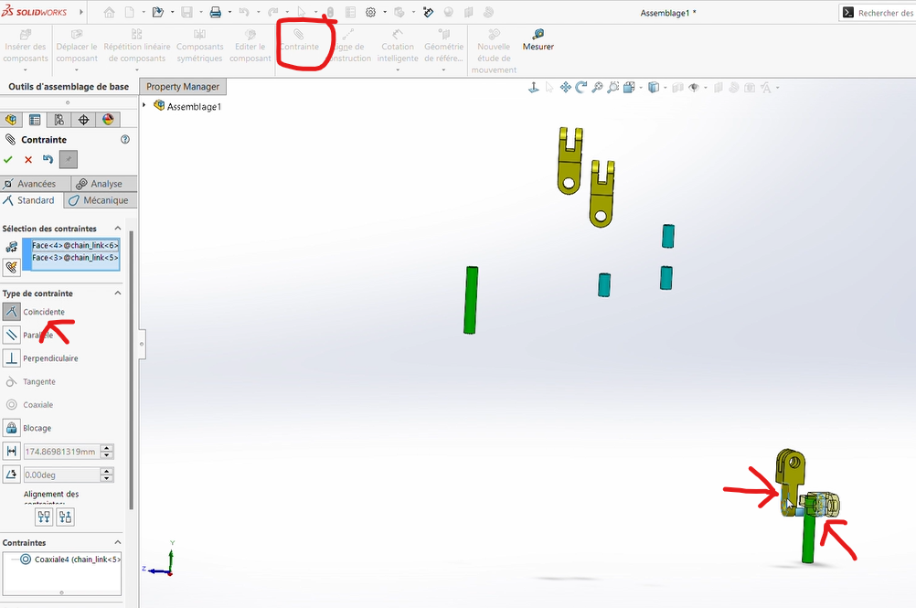
Apply a
Coaxiality Constraintbetween small pin (blue pin) and the shared cavity of the two connectors.Apply a
Coincidence Constraintbetween the external surfaces of the rear connector and the bases of the pin.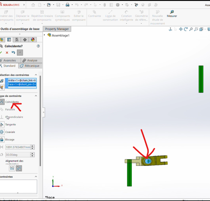
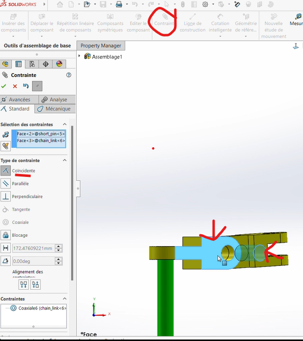
Repeat this process for the remaining two connectors.
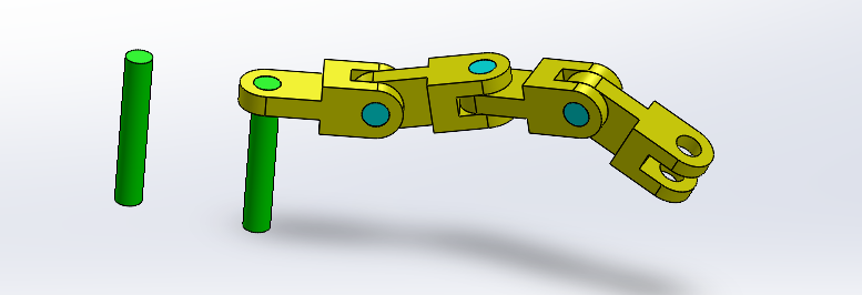
Result
Step 4: Fixing the Last Pin
Fix the second pin to the last free axial end of the final connector.
Process
Follow the same procedure as in Step 2 to attach the second pin.
Coaxiality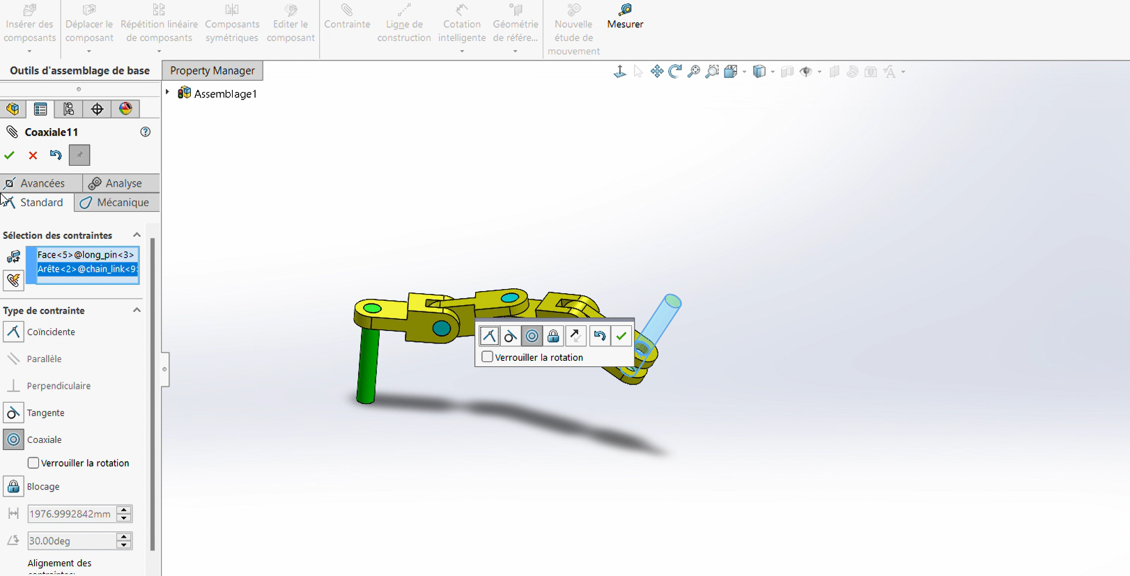
Coincidence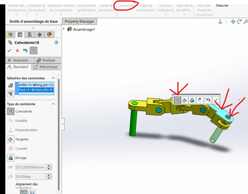
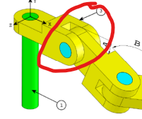
Step 5: Applying Angle Values and Determining the Center of Gravity
Now, we will apply different angle values (A, B, and C) at the joints between connectors and determine the center of gravity for each configuration.
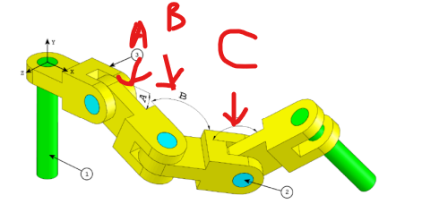
Process
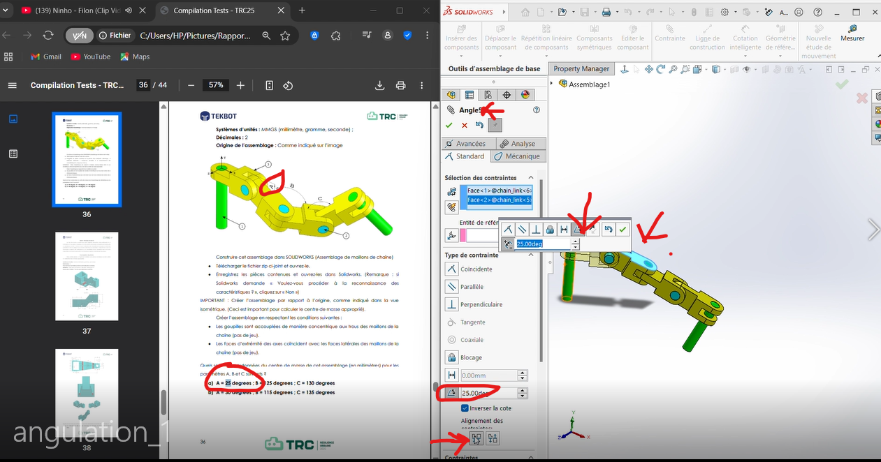
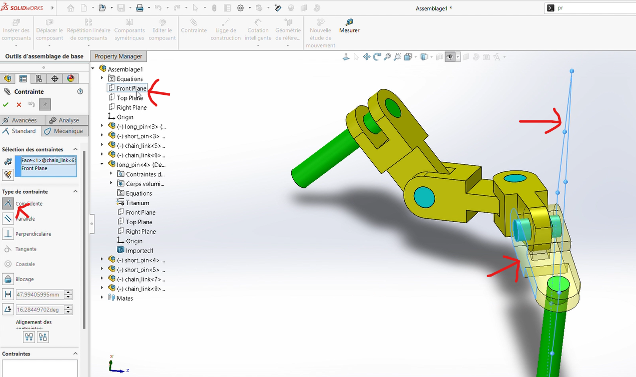
Select in
Constraint, the optionAdd Mate, then choose the faces forming the angles.Apply an angular dimension with the specified values.
First Angle
Second Angle
Third Angle
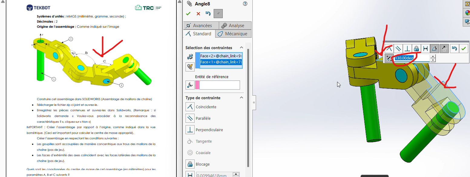
Adjust the angles as needed. Use the
Reverse Dimensionoption if the orientation is incorrect.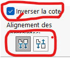
Important Note: Ensure the correct orientation of the connectors. A common mistake is neglecting the fact that the first connector is aligned along the X-axis.
To fix this, apply a
Colinearity Constraintbetween the front plane (already aligned along X) and the opposing face of the connector.
Step 6: Determining the Mass
Finally, determine the center of gravity for the assembly based on the applied angle values.
Process
Click on
Evaluate > Mass Properties.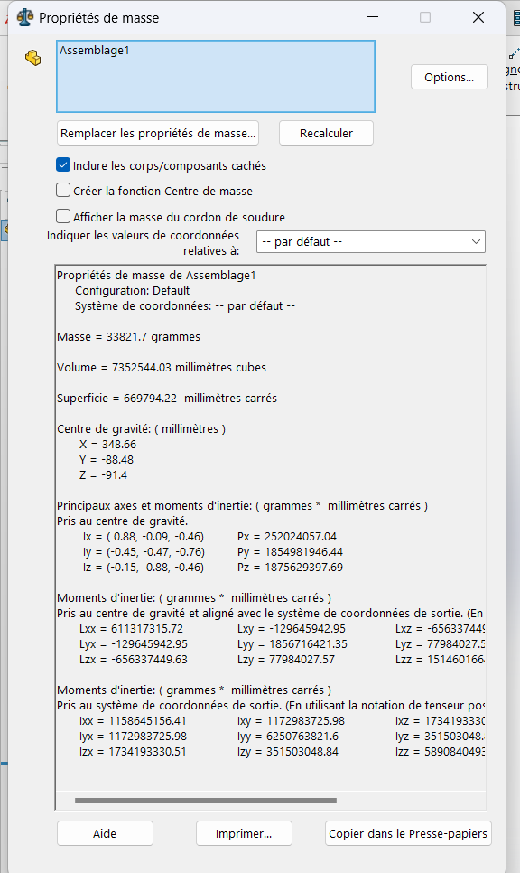
Record the coordinates of the center of mass.
Results:
- For
(A, B, C) = (25°, 125°, 130°):- Center of Gravity:
(X = 348.66, Y = -88.48, Z = -91.40)
- Center of Gravity:
- For
(A, B, C) = (30°, 115°, 135°):- Center of Gravity:
(X = 327.67, Y = -98.36, Z = -102.91)
- Center of Gravity:
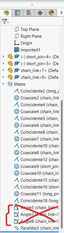
Tip: To switch between angle configurations, delete the existing angular constraints and repeat the process with new values.
Additional Notes
Best Practices:
- Always double-check constraints and alignments before proceeding to the next step.
- Use the
Reverse Dimensionoption to correct orientation issues. - Ensure all pieces are properly constrained to avoid misalignment during assembly.
Troubleshooting:
- If the center of gravity seems incorrect, verify the alignment of the first connector along the X-axis.
- Ensure all angular constraints are applied correctly and consistently.
- The first connection shoulb be aligned to X axis
- you couldn't use global variables to set angular contraints