Documentation for Part 1 of Week 2
Challenge Overview
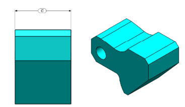
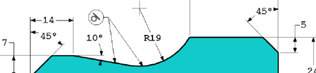
This challenge involves creating the part shown below using SolidWorks, adhering to the provided measurements, dimensions, and constraints. The dimensions A, B, and C are treated as variables, and the objective is to determine the mass of the part based on the values assigned to these variables.
Short Demo
Link to Download: Link to download
Design Steps
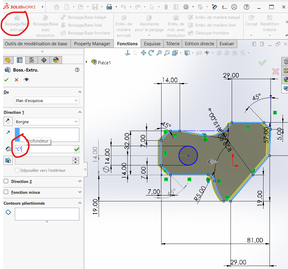
Step 1: Creating the Base Sketch
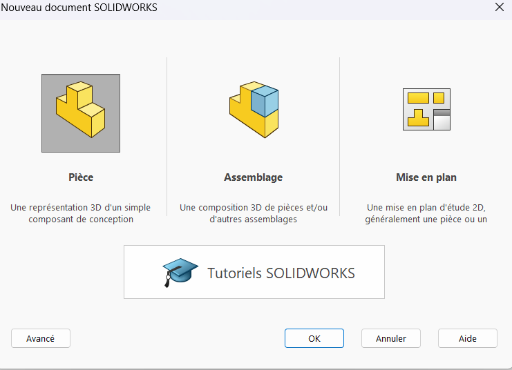
To begin, open a new part in SolidWorks by clicking the "New" icon, selecting "Part," and clicking "OK."
Configure Units
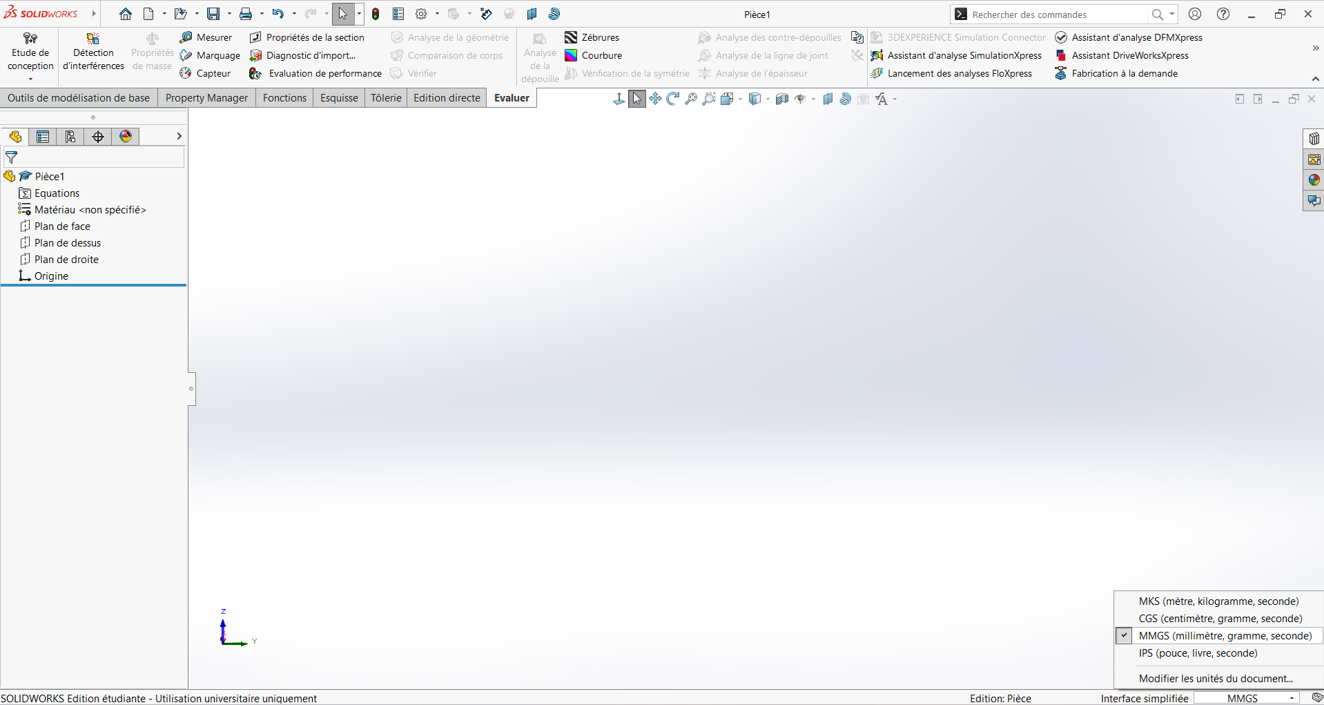
Set the unit system to MMGS (Millimeter, Gram, Second).
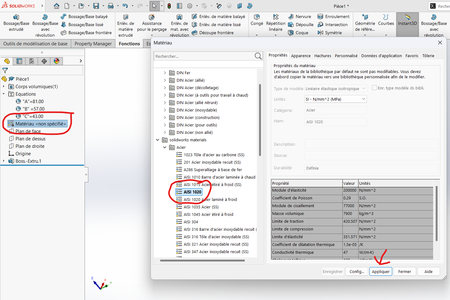
Define Global Variables
To evaluate the variation in mass based on parameters A, B, and C, define these as global variables:
- Go to Tools > Equations.
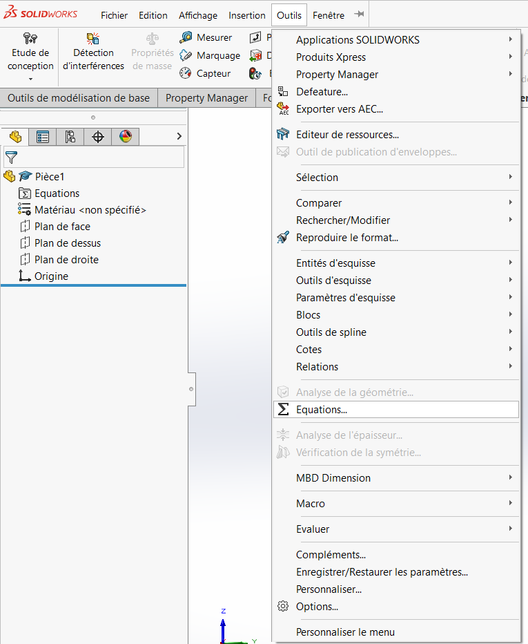
- In the table that appears, insert your variables and their values. Start with the default values provided in the PDF.
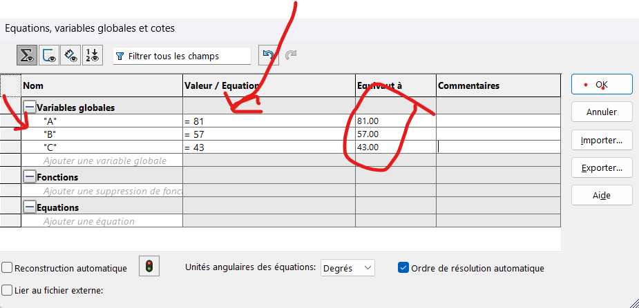
Example:
- Variable Name:
"A", Value:84 - Variable Name:
"B", Value:57 - Variable Name:
"C", Value:43

Tip: Ensure correct syntax when defining variables (e.g.,
"A"for the name and=84for the value).
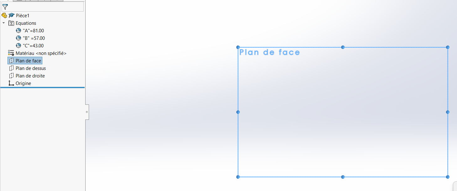
Select a Drawing Plane
Choose a plane to start sketching. For this design, we’ll use the Front Plane.
Draw the Outline
Sketch all the edges of the figure, including the circle specified in the diagram.
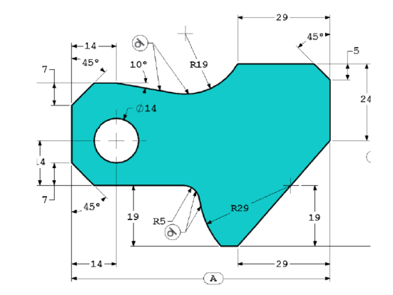
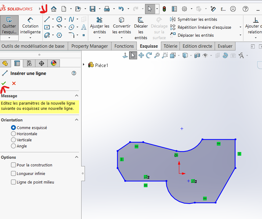
Apply Dimensions
Use the Smart Dimension tool to apply the required dimensions. Select the edges or features you want to dimension and input the corresponding values.
Demo of a proocess
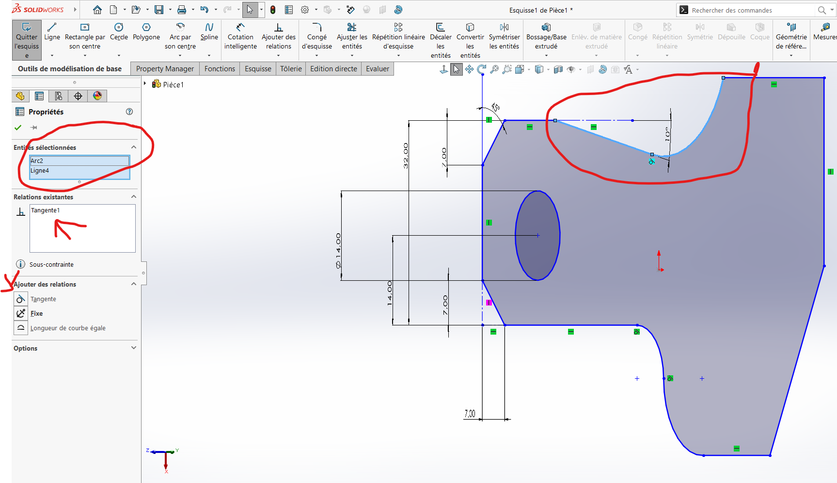
**Add Tangency Relations
Apply tangency relations to the specified areas.
Step 2: Extrusion
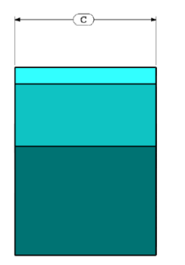
Once the base sketch is complete, extrude it to add material. Use the global variable C as the extrusion height.
- Go to Features > Extruded Boss/Base.
- Input the global variable
Cin the dimension field. - Select both the outer contour and the circular cutout to ensure simultaneous extrusion.
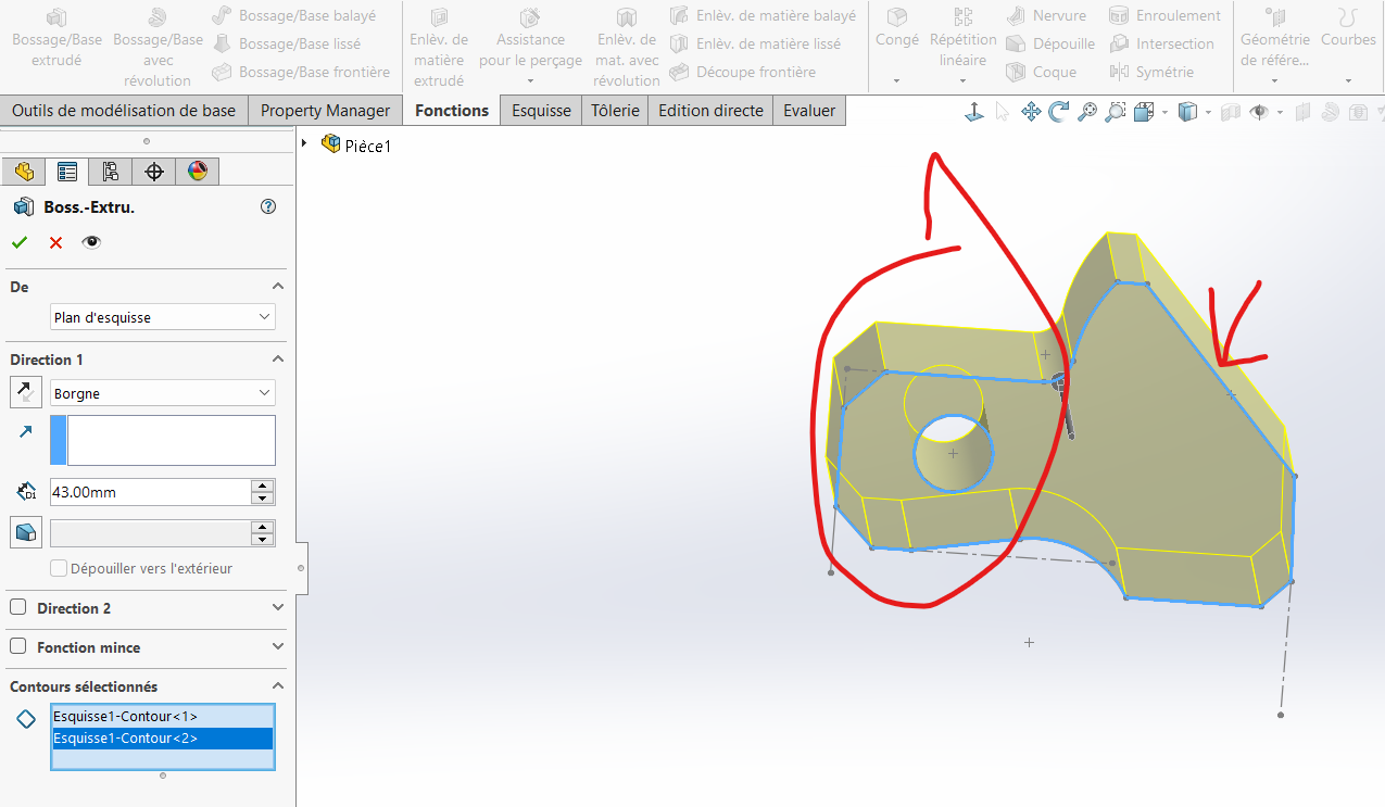
Note: Extruding the circular cutout along with the base simplifies the process and avoids additional steps later.
Step 3: Assign Material
Assign the material AISI 1020 Steel to the part:
- Click the
Materialicon in the left-hand panel. - Select
AISI 1020 Steelfrom the list.
Step 4: Evaluate Mass
To calculate the mass of the part:
- Go to Evaluate > Mass Properties.
- Review the calculated mass.
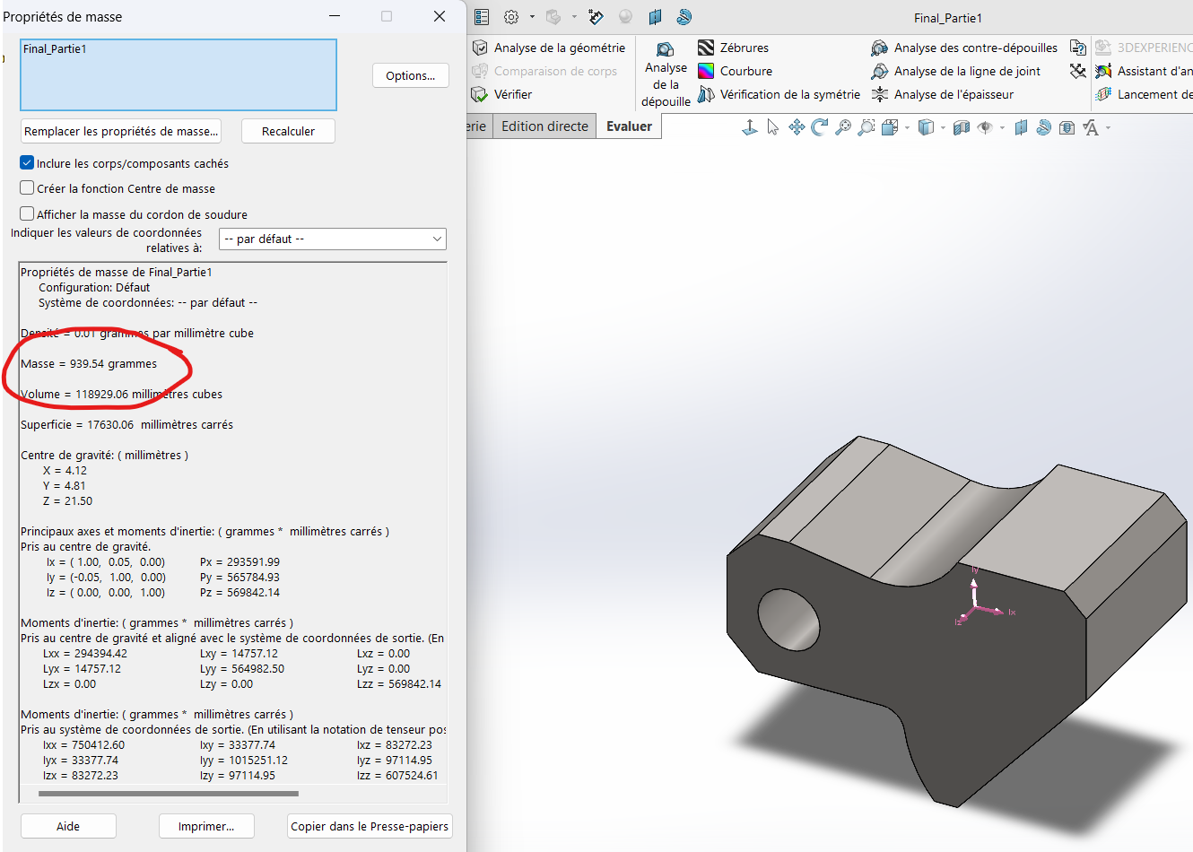
Results:
- For
(A, B, C) = (81, 57, 43): Mass = 939.54 g - For
(A, B, C) = (84, 59, 45): Mass = 1032.32 g
Tip: To modify the values of
A,B, orC, return to the Equations table and adjust as needed.
Additional Notes
- Best Practices:
Always double-check dimensions and tangency relations before extruding. ß
Ensure that you don't overlook any single quotation
Always verify that you are using mmgs.
Maintain proper syntax for global variables.