Documentation of the Bonus Part Introduction
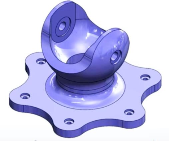
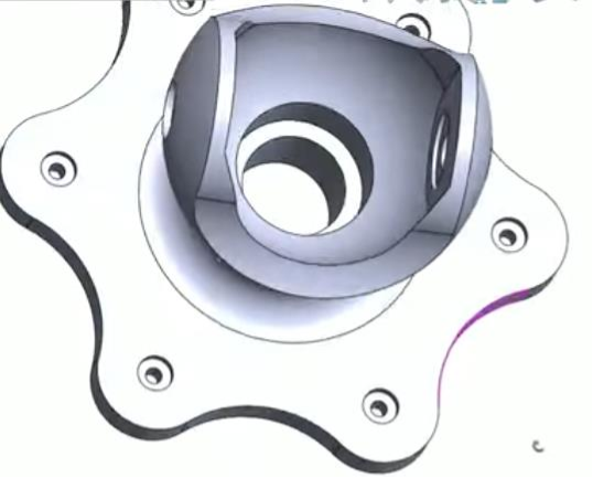
This part, designed by TEKBOT as part of the TRC Urban Resilience project, is an articulated support used in mechanical assemblies. It consists of a star-shaped base with holes for fastening, ensuring optimal stability. The upper section features a half-shell structure designed to hold a pin or a ball joint, allowing angular movements. Its geometry combines curved shapes and machined surfaces, ensuring both strength and precision.
Piece to be made
Here is a step-by-step guide to making this piece :
Step One : Creating the Solid Base

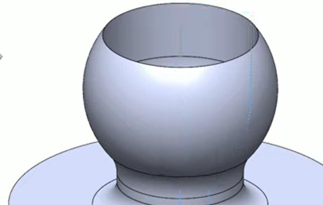
3 Description
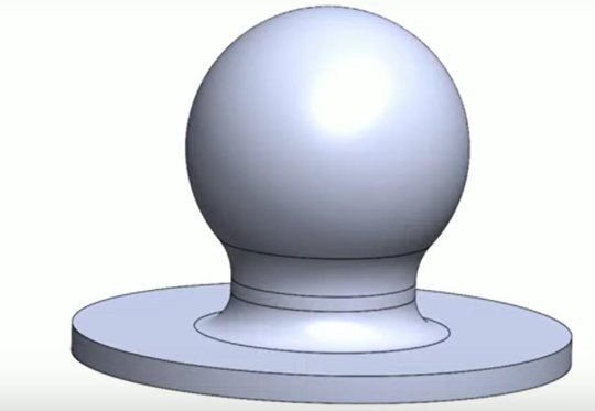
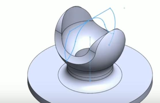
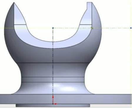
This step shows the piece with its circular pass, a torso and a head in the shape of a balloon. To achieve this, follow these steps :
How to achieve this ?
Actions
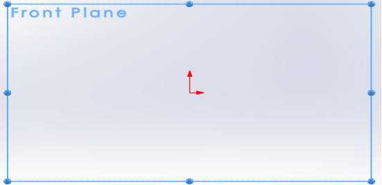
Selection of the XY plane, particularly called Front Plane in SolidWorks.
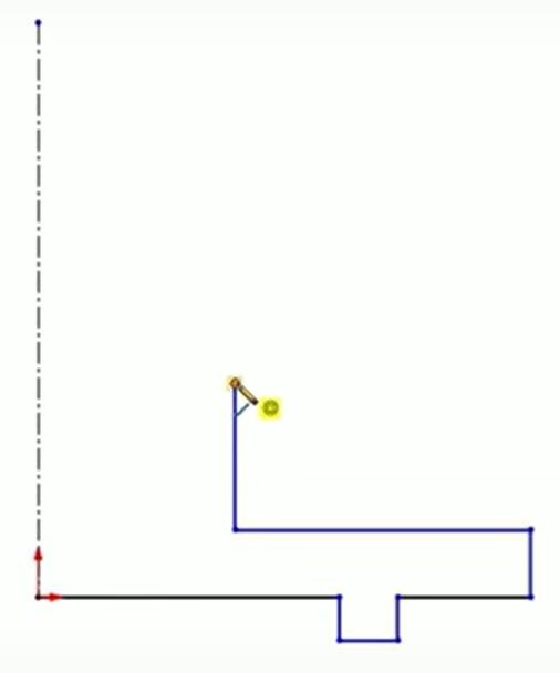
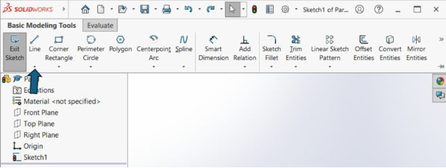
We will start by drawing line segments in order to give a precise shape to our solid. Follow these steps:
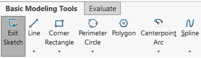
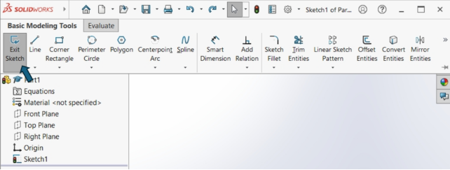
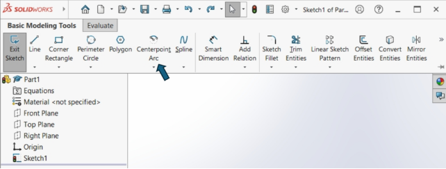
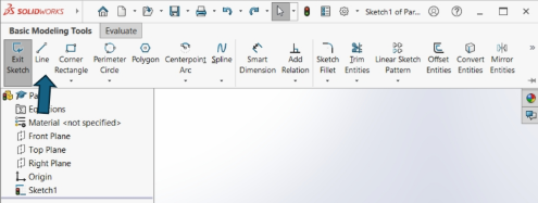
- Click on then in the window that opens choose the line option

- Position your cursor at the origin of your reference point then represent the 2D rectangle without taking into account the dimensions as follows :
4
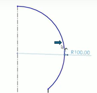
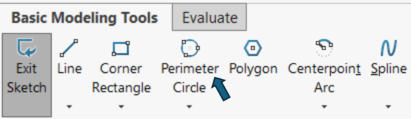
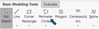
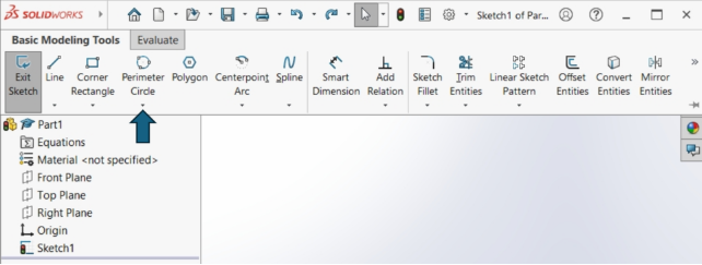
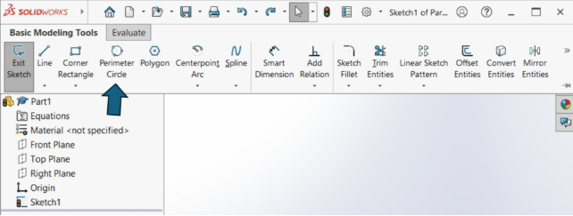
After that, click on then in the window that opens choose the Perimeter Circle option
After that do this:
5
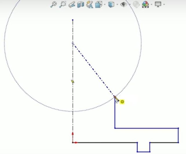
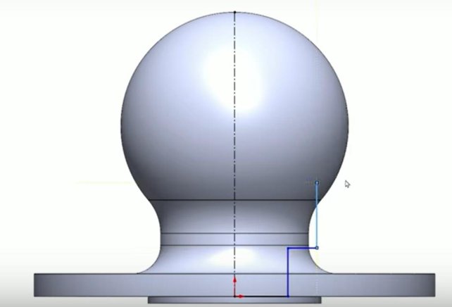
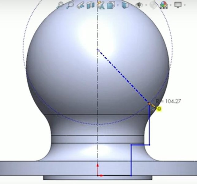
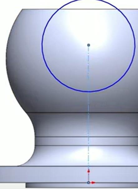
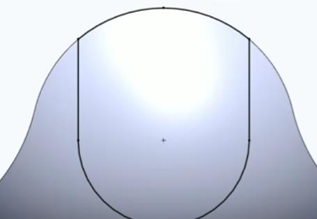
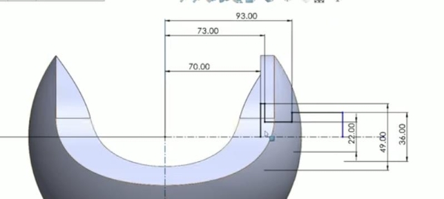
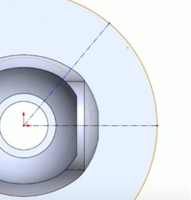
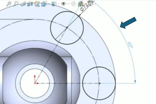
Hold your pencil in this position and then draw a half-curve as in the following figure:
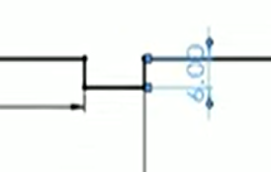
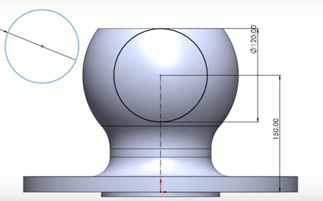
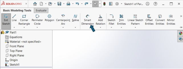
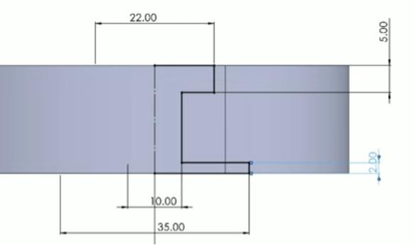
- After that we will assign the dimensions. To do this, click on Smart Dimension to automate the dimensions :
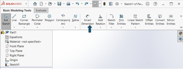
This function will allow you to automate the measurement of dimensions by modifying them yourself; you just need to click on the line you want to resize, hold the click in the desired direction.
Illustration 

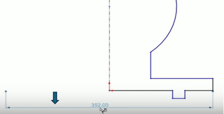
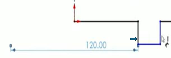
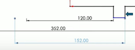
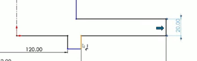
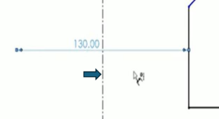
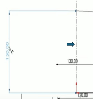
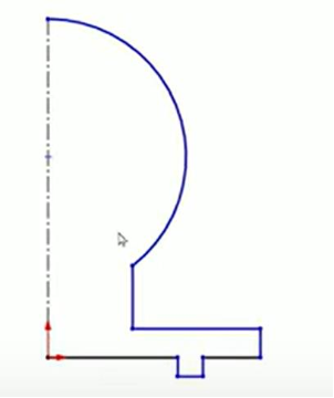
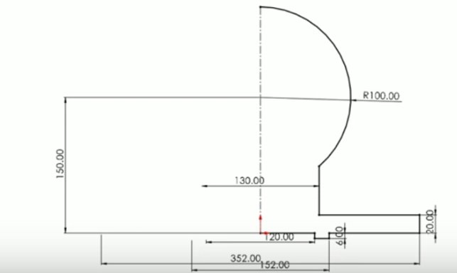
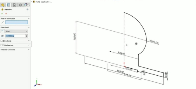
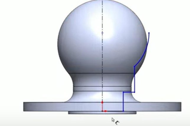
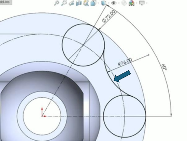
- Observe carefully the dimensions assigned to each line segment and apply them. Result
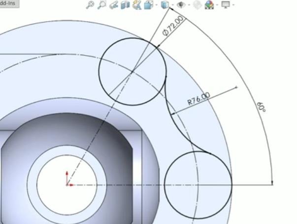
The form gives this diagram:
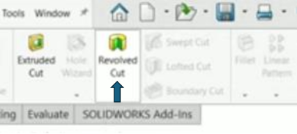
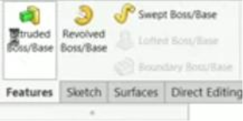
- After that, click on then in the window that opens choose the Revolved Boss/Base option
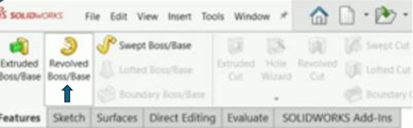
You must obtain this interface :
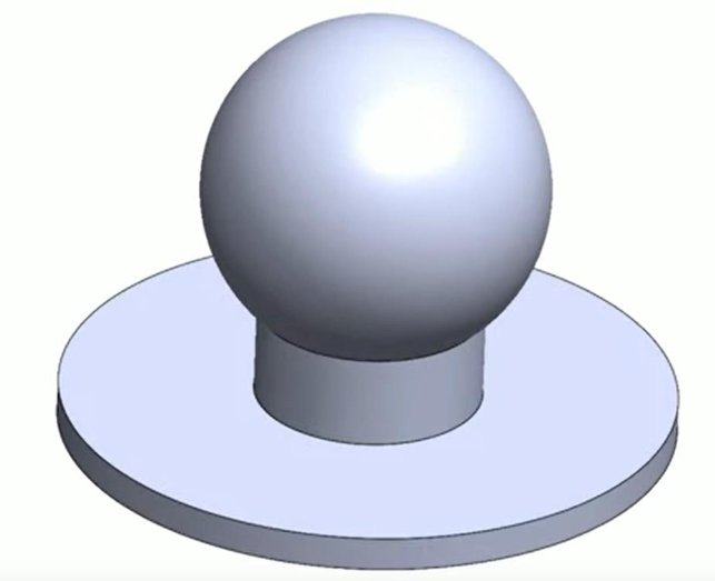
By clicking on the validation button you should now get this::
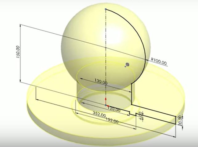
Result
The circle or rather the basic solid of our part is created, representing the initial gross volume of the part.
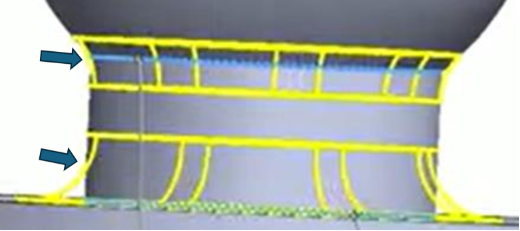
Step Two : Create the nets
13 Description
In this step, we will create the nets that are on the trunk of our current solid. How to achieve this ?
Actions
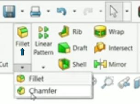
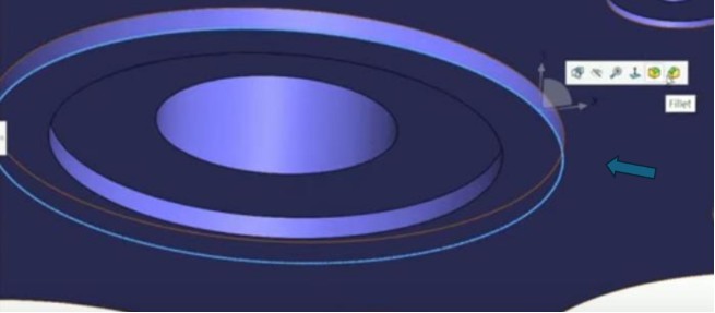
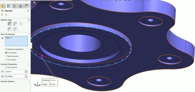
- Click on then in the window that opens choose the Fillet option
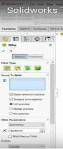
You should obtain this parameter :
Take these details into account in particular

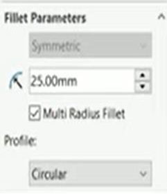
15
After that you must obtain the current figure :
You will then obtain the figure from step 2
Step Three : Central hollow
Description
At this stage, you must create a follow.
How to do it ?
16
Actions
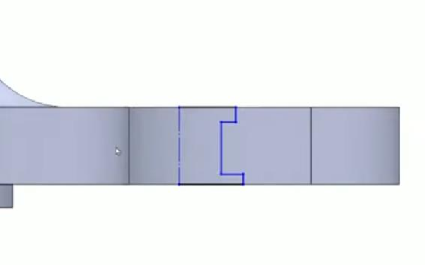
- Click on then in the window that opens choose the line option

- Position your cursor at the origin of your reference point then represent the 2D rectangle without taking into account the dimensions as follows :
- After that, click on then in the window that opens choose the Perimeter Circle option
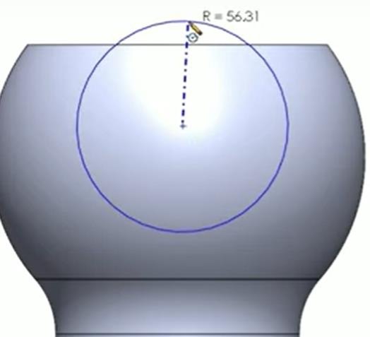
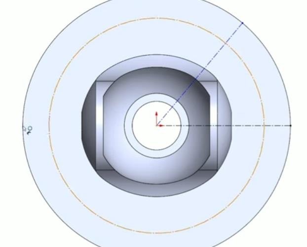
After that do this:
Hold your pencil in this position and then draw a half-curve as in the following figure:
After that we will assign the dimensions. To do this, click on Smart Dimension to automate the dimensions :
This function will allow you to automate the measurement of dimensions by modifying them yourself; you just need to click on the line you want to resize, hold the click in the desired direction.
Illustration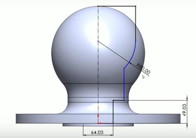
Make sure you can respect all the dimensions taken to obtain a good result.
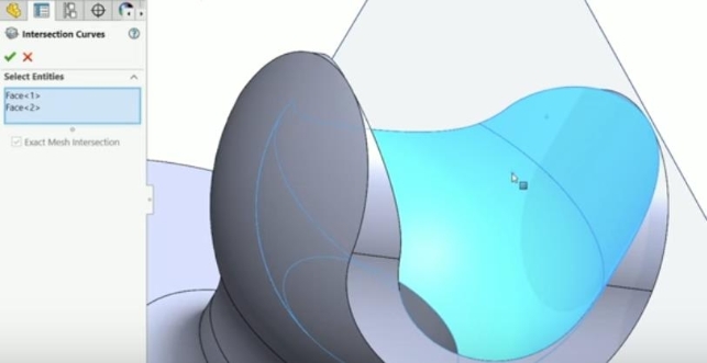
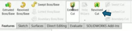
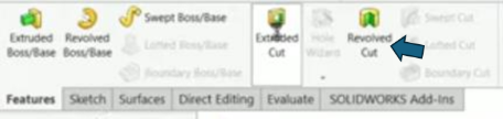
Selects the Revolved cutting functionality
You must obtain this interface
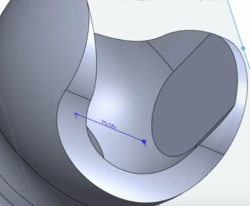
Result
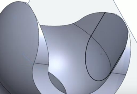
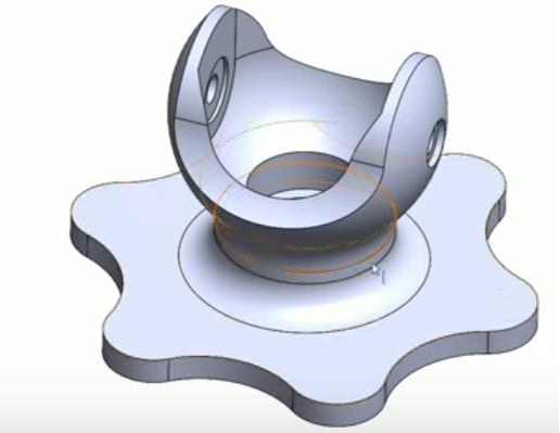
Final result :
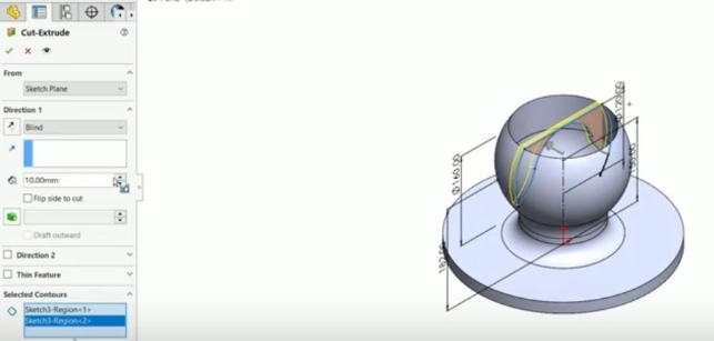
Step Forth : Hollow arranged on either side of the balloon
Description
For step you must draw the hollows arranged on either side of the ball.
How to do it ?
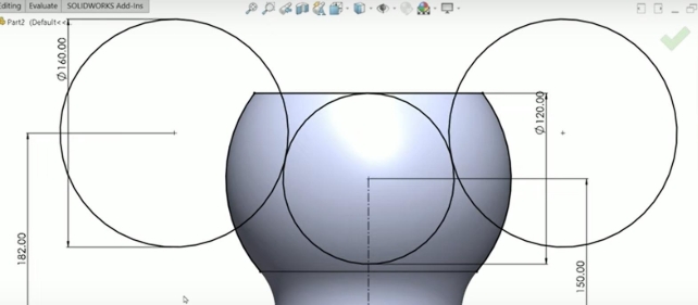
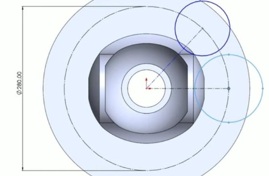
- Click on then in the window that opens choose the Perimeter Circle option
After that do this :
After that click on then in the window that opens choose the Perimeter Circle option
Position your cursor at the origin of your reference point then represent the 2D rectangle without taking into account the dimensions as follows :
Click on then in the window that opens choose the Perimeter Circle option and draw draw a circle as shown in the following figure
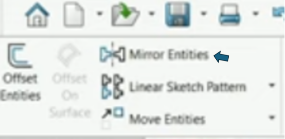
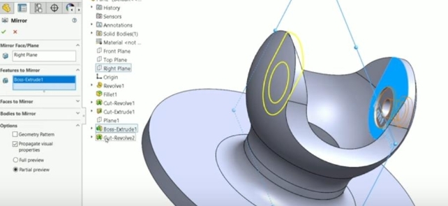
To get the circle on the other side of the ball you would need to use the Mirror Entities functionality of SolidWorks
To do this, click here :
After that you should get this figure :
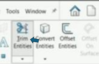
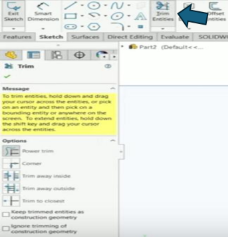
- After that select the option Trim Entities oh SolidWorks as shown in this figure :
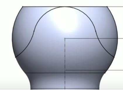
Thanks to this functionality, remove the unitary parts to obtain the following solid:
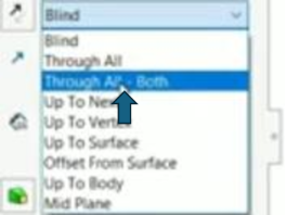
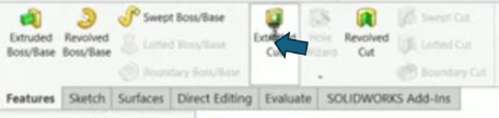
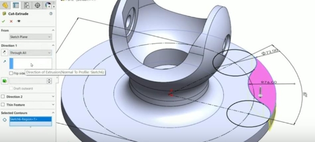
- Click on then in the window that opens choose the Extruded Cut option

- You must also activate this option :

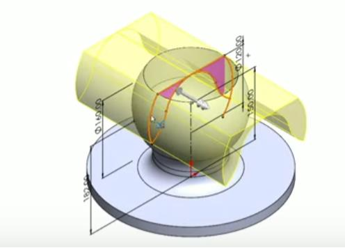
And you must obtain this figure :
NB : Take these details into account in particular
If everything is done correctly you should get a figure like this :
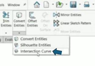
- After that select the Convert Entities Fonctionalities of SolidWorks :
- You obtain this figure :
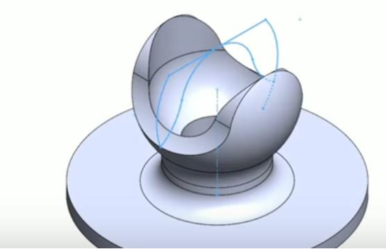
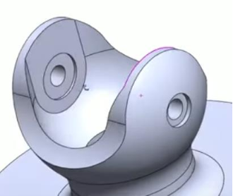
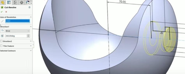
Result
Here is the final diagram that we obtain at the end of this step :

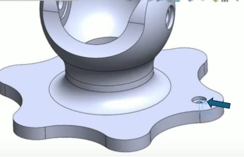
Step Forth : Bolt hollows 
Description
For step you must draw the bolt hollows arranged on either side of the ball. How to do it ?
- Click on then in the window that opens choose the Trim Entities option
- You must obtain this figure :
After that click on the option Extruded Boss/Bass of SolidWorks :
This interface should be display in your screem 1-
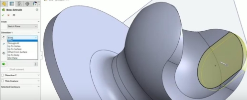
2- 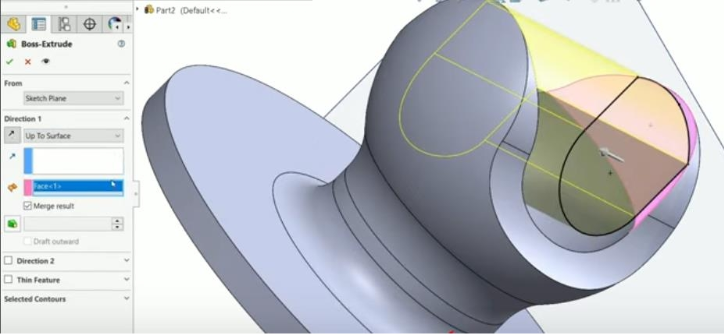
3-
- Click on then in the window that opens choose the line option

Position your cursor at the origin of your reference point then represent the 2D rectangle without taking into account the dimensions as follows :
1-
2-
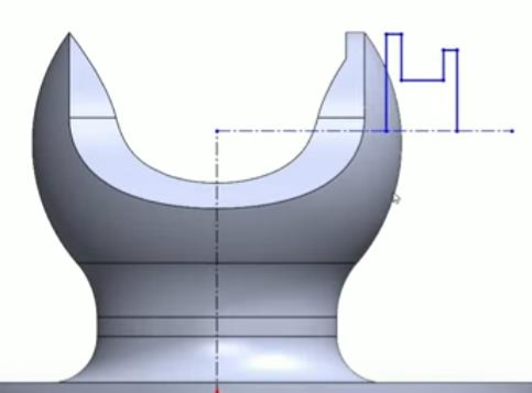
- After that we will assign the dimensions. To do this, click on Smart Dimension to automate the dimensions :
34 
This function will allow you to automate the measurement of dimensions by modifying them yourself; you just need to click on the line you want to resize, hold the click in the desired direction.
Illustration
Make sure you can respect all the dimensions taken to obtain a good result.
- Click on then in the window that opens choose the Removed Cut option
You must obtain this figure : 1-
35
2-
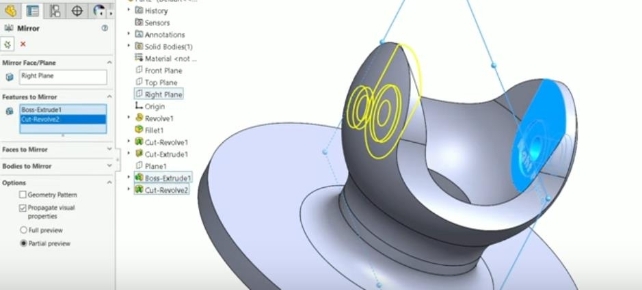
- To get the circle on the other side of the ball you would need to use the Mirror Entities functionality of SolidWorks
To do this, click here :
36

After that you should get this figure :
1-
2-
3-
Step six : Bolt hollows
Description
For step you must draw the hollows arranged on either side of the base of our solid.
How to do it ?
- Click on then in the window that opens choose the line option
Position your cursor at the origin of your reference point then represent the 2D rectangle without taking into account the dimensions as follows :
1-
- Click on then in the window that opens choose the line option
2-
- After that we will assign the dimensions. To do this, click on Smart Dimension to automate the dimensions :
41
Position your cursor at the origin of your reference point then represent the 2D rectangle without taking into account the dimensions as follows :
Draw circles on either side of the vertices of the triangle drawn as shown in the following figure :
42
- After that we will assign the dimensions. To do this, click on Smart Dimension to automate the dimensions :
We will draw two different arcs as illustrated in the two figures below :
43
1-
2-
This function will allow you to automate the measurement of dimensions by modifying them yourself; you just need to click on the line you want to resize, hold the click in the desired direction.
Illustration
- Click on then in the window that opens choose the Extruded Cut option
And you must obtain this figure :
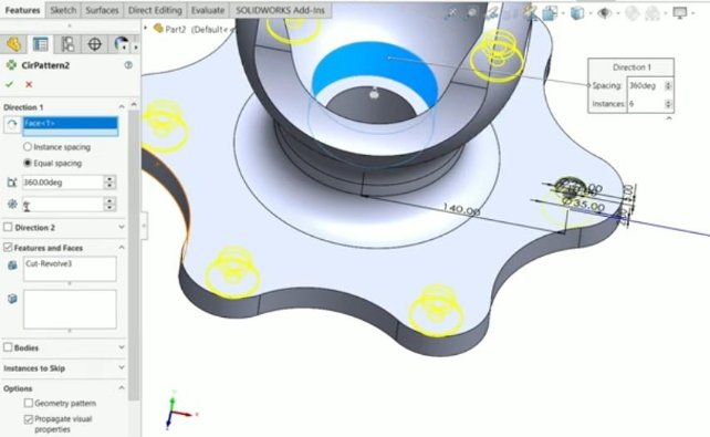
- Click on then in the window that opens choose the Linear Pattern option
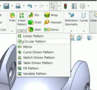
And you must obtain this interface :
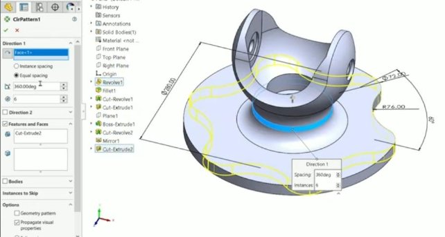
Result
Final Step : Bolt hollows of the base
Description
For step you must draw the hollows arranged on either side of the base of our solid.
How to do it ?
Click on then in the window that opens choose the line option
Position your cursor at the origin of your reference point then represent the 2D rectangle without taking into account the dimensions as follows :
- After that we will assign the dimensions. To do this, click on Smart Dimension to automate the dimensions :
- Position your cursor at the origin of your reference point then represent the 2D rectangle without taking into account the dimensions as follows :
- Click on then in the window that opens choose the Removed Cut option
And you must obtain this figure :
- Click on then in the window that opens choose the Linear Pattern option
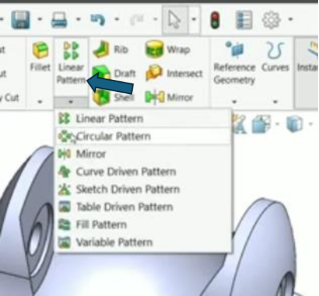
And you must obtain this interface :
- The last action :
- Apply the "Net" functionality to your part base as illustrate on this figure :
- You should obtain this intarface :
Final Result
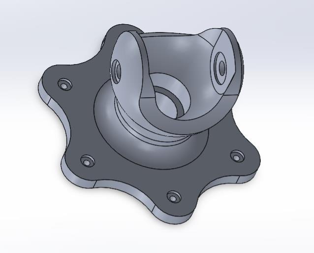
Get the mass of our part
How to do it ?
Actions:
Click on then in the window that opens choose the Removed Cut option
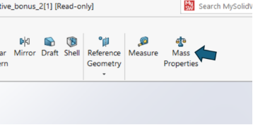
You will see a window open containing the result of the calculation of the mass of our solid.
This window looks like this:
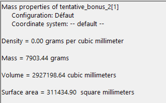
Mass of the Part: Mass = 7903.44 grams 54