Documentation of the Construction of piece III
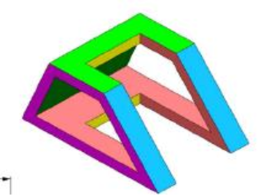
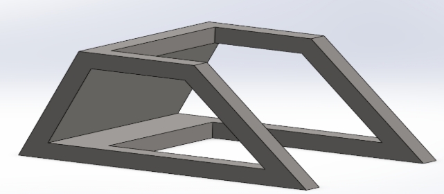
Part III, designed by TEKBOT as part of the TRC Urban Resilience project, is an AISI 1020 steel structure intended to serve as a support or connection in mechanical or architectural assemblies. Its geometry is based on an assembly of prismatic square-section profiles, designed to ensure rigidity and lightness. The different faces of the part—plan representation, isometric view, and section— allow a complete understanding of the shape and critical dimensions before manufacturing.
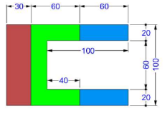
Piece to be made
Short Demo
Link to Download: Link to download
Here is a step-by-step guide to making this piece:
Step One : Creating the Solid Base
Description
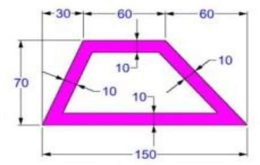
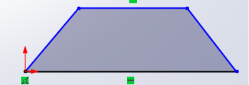
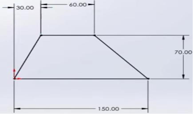
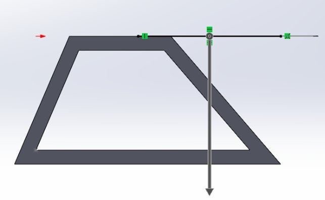
This step shows an isosceles trapezoid and is the very first to be performed, ensuring a good foundation for our piece. To do this, do the following:
Actions
- Selection of the XY plane, particularly called Front Plane in SolidWorks.
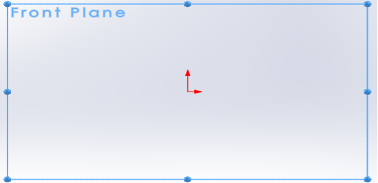
- Drawing a 2D rectangle with the following dimensions :
- Length : 150,00 mm
- Width : 70,00 mmHow to achieve this?
Follow these steps:
- Click on then in the window that opens choose the line option
![]()
- Position your cursor at the origin of your reference point then represent the 2D rectangle without taking into account the dimensions as follows :
- After that we will assign the dimensions. To do this, click on Smart Dimension to automate the dimensions :
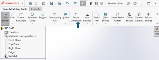
This function will allow you to automate the measurement of dimensions by modifying them yourself; you just need to click on the line you want to resize, hold the click in the desired direction.
Illustration
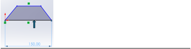
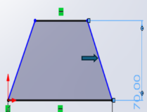

- The dimensions therefore comply with the requirements.Mesures
- Trapezoid length : 150,00 mm
- Trapezoid width : 70,00 mm
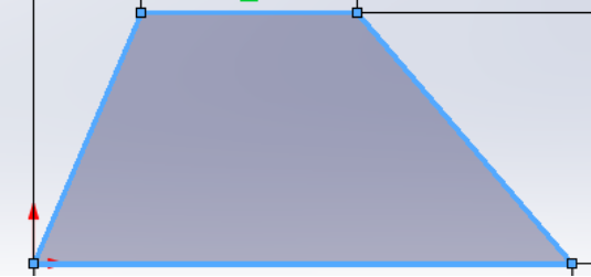
Result
A 2D rectangle with dimensions 150.00 mm × 70.00 mm is created, representing the base of the part.
Step Two : Extruding the Base to Form a Prism
Description
Transformation of the 2D trapezoid into a 3D solid by extruding it to give it a height, corresponding to the total height of the initial part.
How to do it ?
Actions
- Selection of the current 2D trapezoid.
- Using the Offset Entities tool to double your trapezoid.
![]()
- Set the extrusion height to 10.00 mm.
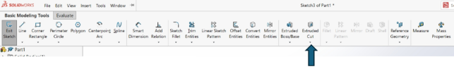
- Using the extrusion tool
![]()
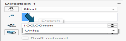
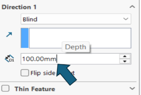
Select the current figure then click on the function Extruded Boss/Base. You will get an interface like this :
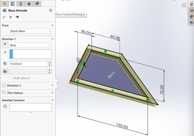
Change the value according to the requirements. In our case we must use 100.00 mm
- After this modification you will get a figure like this:
Measures
- Prism length : 150,00 mm
- Prism width : 70,00 mm
- Prism height : 10,00 mm
Result
A rectangular prism with dimensions 150.00 mm × 70.00 mm × 100.00 mm is created, representing the initial gross volume of the part.
Step Three : Triangular Cut on the Upper Face
Description
At this stage, you need to add a triangular cutout on the upper face of the prism.Comment s’y prendre ?
Actions
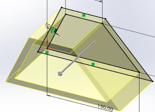
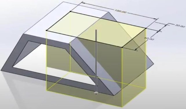
In a Front Plane, select the top face of the prism (150.00 mm × 70.00 mm). In this illustration, the top face of the prism is the one in blue.
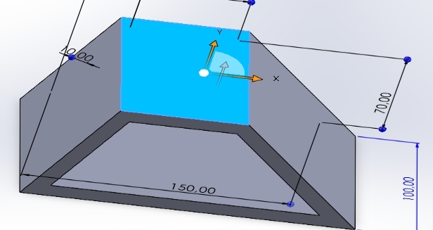
Drawing a 2D triangle on this face :
Cutting length : 100,00 mm
Cutting width : 60,00 mm
Cutting depth : 20,00 mm
Let's do it, step by step:
First select the current figure :

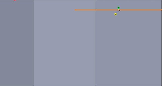
Select the line function to perform the drawing
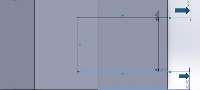
Draw the horizontal line (100.00 mm)
Draw the vertical line (20.00 mm)
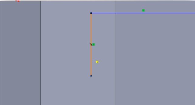
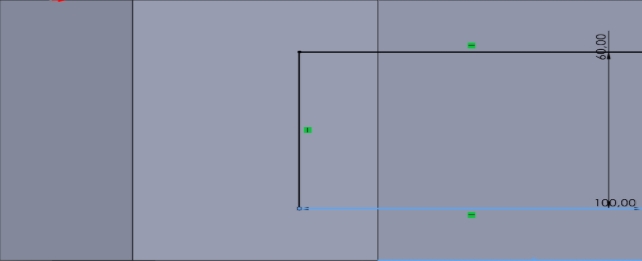
Draw the second horizontal line in the image of the first We obtain the following :
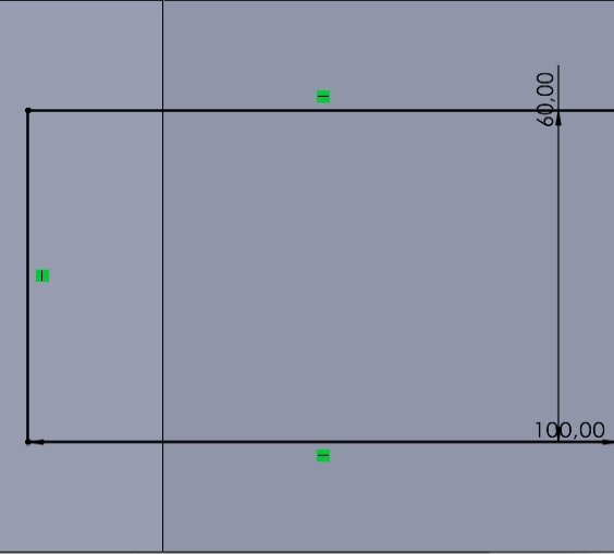
Next, we'll apply the Cutout Depth: 20.00 mm
Use SolidWorks' Smart Dimension feature once again to automate dimension measurement.
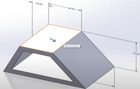
Result
The prism has a triangular cutout on its upper face, leaving a 20.00 mm border on each side along the width.
Step Four : Central Rectangular Cutout
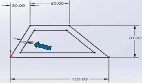
Description
At this stage, you need to add a central rectangular cutout.
How to do it?
Actions
- Selection of the upper face of the prism, in the area defined by the triangular cutout.
- Using the extrusion cutting tool to remove this triangular shape to a depth of 100.00 mm.
- Selects the extrusion cutting functionality
- Changes the depth of this extrusion (100.00 mm)
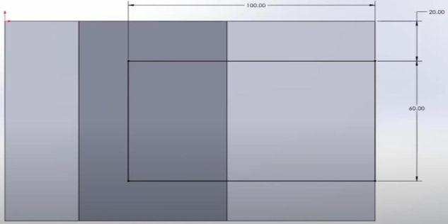
You will get a figure like this:
After validating your extrusion you will obtain the final result.
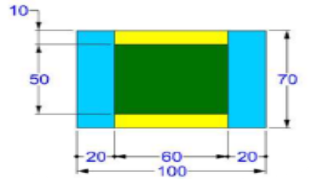
Measures
- Cutout Length : 100,00 mm
- Cutout Width : 60,00 mm
- Cutout Depth : 20,00 mm
Result
A rectangular cutout of 100.00 mm × 60.00 mm × 20.00 mm is added to the center of the prism.
Step Five : Final Adjustments and Penrose Triangle Transformation
Description
This step is the final one, showing the solid in its final phase. The part is manufactured from AISI 1020 steel (density: 0.0079 g/mm³), using the MMGS system and an accuracy of two decimal places. AISI 1020 offers a good compromise between strength, ductility, and cost, ideal for this type of component. Density is specified to calculate weight, a key factor in design and transport. Precision and the MMGS system ensure uniform and reliable manufacturing.
Final result
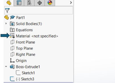
How to change the appearance of the part to AISI 1020?
Follow these steps :
- On the interface SolidWorks click on Material not specified then a window will open
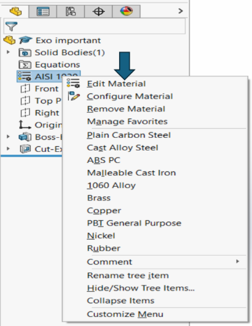
- This is what this window looks like, choose the option Edit Material then click on it and a window will open
- This is what this window looks like. In the list of materials, choose the one required in our case, it will be AISI 1020
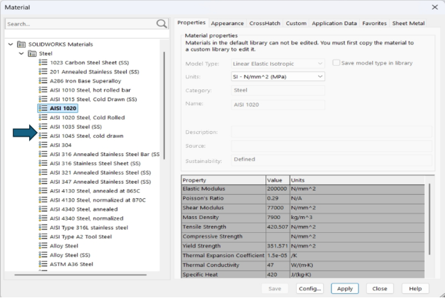
In this case it is not necessary to modify the density ; it cannot be modified ; its value remains and remains at : 0.0079 g/mm³.
How to calculate the mass of this solid ?
Follow these steps :
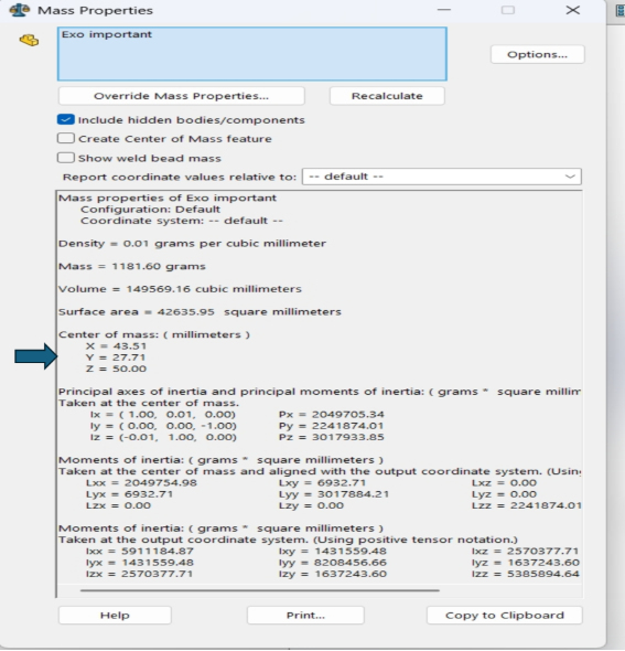
- On the SolidWorks interface click on the Mass Properties feature click on it and a window will open
This is what this window looks like. In this window you will see the calculations made including the mass of the solid in our case the mass of the part is as follows : Mass = 1181.60 grams