Documentation of the Mechanical Design of the Conveyor System
The objective of this challenge was to bring together all the skills we acquired during previous challenges to design an intelligent and efficient autonomous conveyor. To achieve this, we first brainstormed and sketched out ideas for what the conveyor would look like. The conveyor had to be 650mm long and 100mm above the ground. It also had to be modeled in SolidWorks. The process took two directions: the ideation phase, marked by virtual design, and the physical construction phase. This documentation details the process we followed during these phases, the mechanical constraints we encountered, and how we overcame them.
Virtual Design Phase
Overview of the Virtual Design Process
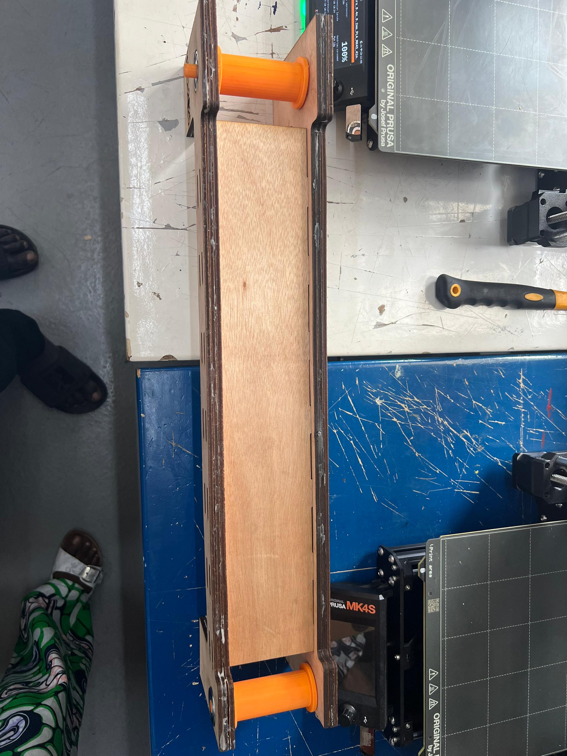
The virtual design focused on SolidWorks for 3D modeling and Illustrator for sketches intended for laser cutting. The conveyor had to be 650mm long, with the belt positioned 100mm above the ground. First, we had to think about how our conveyor would stand. We opted for two parallel vertical supports connected by horizontal planks to ensure balance. A final horizontal plate was added to keep the entire structure fixed and sturdy.
Support
Key Components and Design Process:
Vertical Support
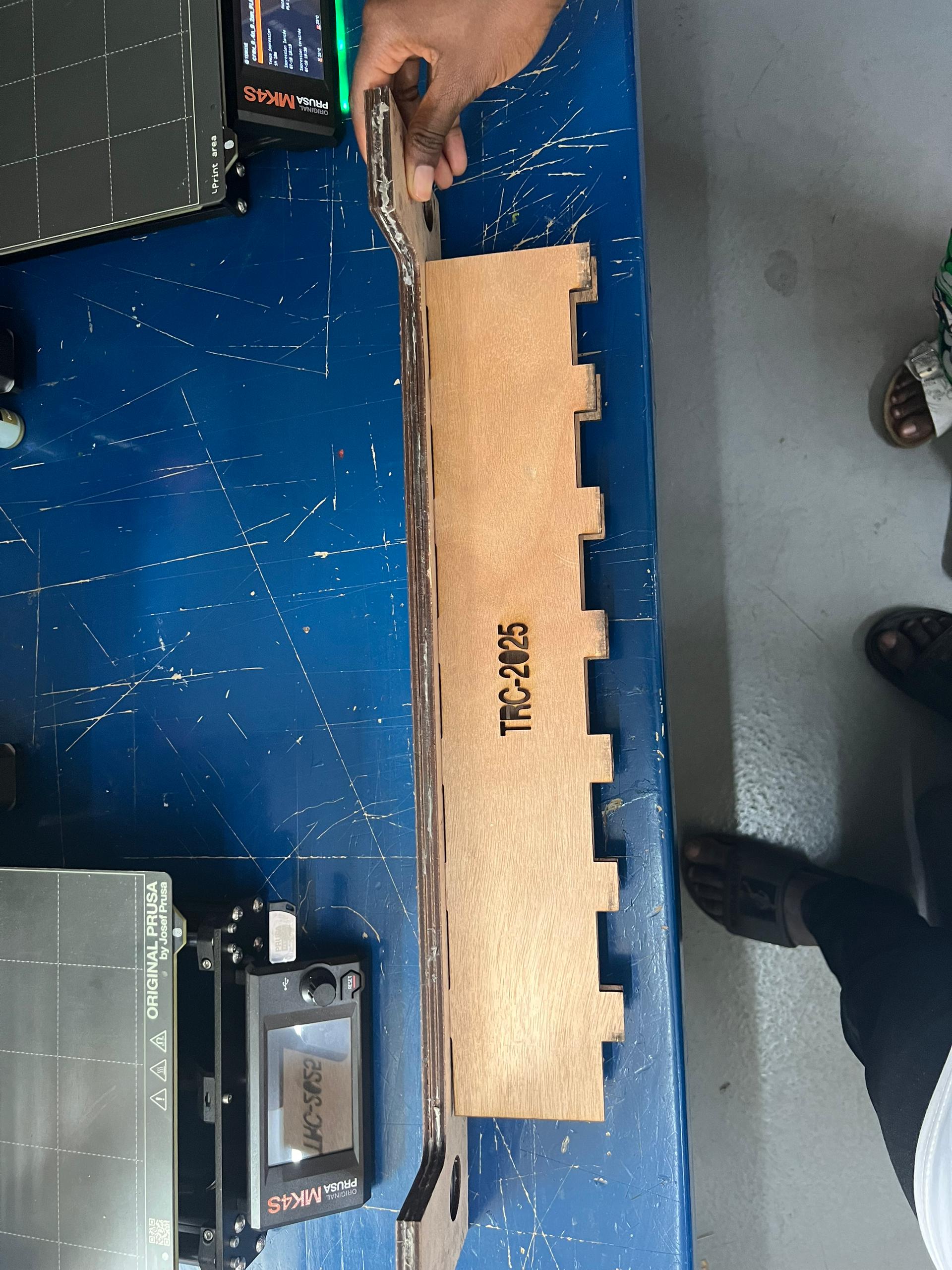
This is the vertical face that supports the entire assembly. It has a height of 115mm to comply with the challenge requirements. The 1mm difference is to provide a small margin. Initially, we planned to use wood, but the workspace of our laser cutter is limited to 600x300mm boards. Therefore, instead of 650mm plates, we opted for 590mm, giving us a 60mm margin.
Features:
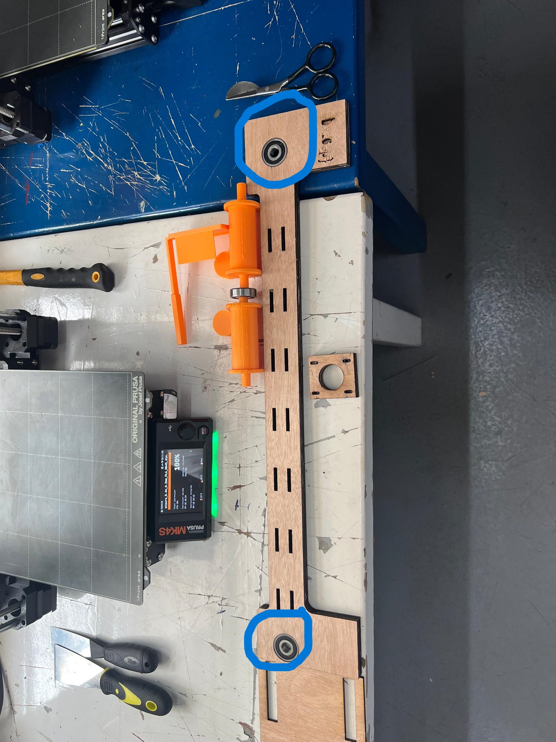
Two rows of small cavities to mount horizontal supports. Circular holes at the ends (30mm diameter) for inserting bearings to smooth the drum's rotational movement.
Design prcecess:
- Horizontal Support:
These are two surfaces placed on the two rows of cavities carved into the vertical supports, perpendicular to them, maintaining balance. They also act as stabilizers for the conveyor belt, preventing overloads and blockages. They are positioned around the drum for easy deployment above and below the belt. We chose a spacing of 70mm between the plates, making the support measure (70 + 12 * 2) 94mm wide (including the interlocking parts) and 450mm long.
Base Support:
This is the base on which the entire assembly rests. It consists of cavities to hold the vertical supports. Due to the laser cutter's workspace limitations, we segmented it into two complementary surfaces. In addition to supporting the structure, it serves as a base for components under the conveyor and allows us to extend the missing 60mm to reach the total length of 650mm.
Assembly Process:
Conveyor Mobility System
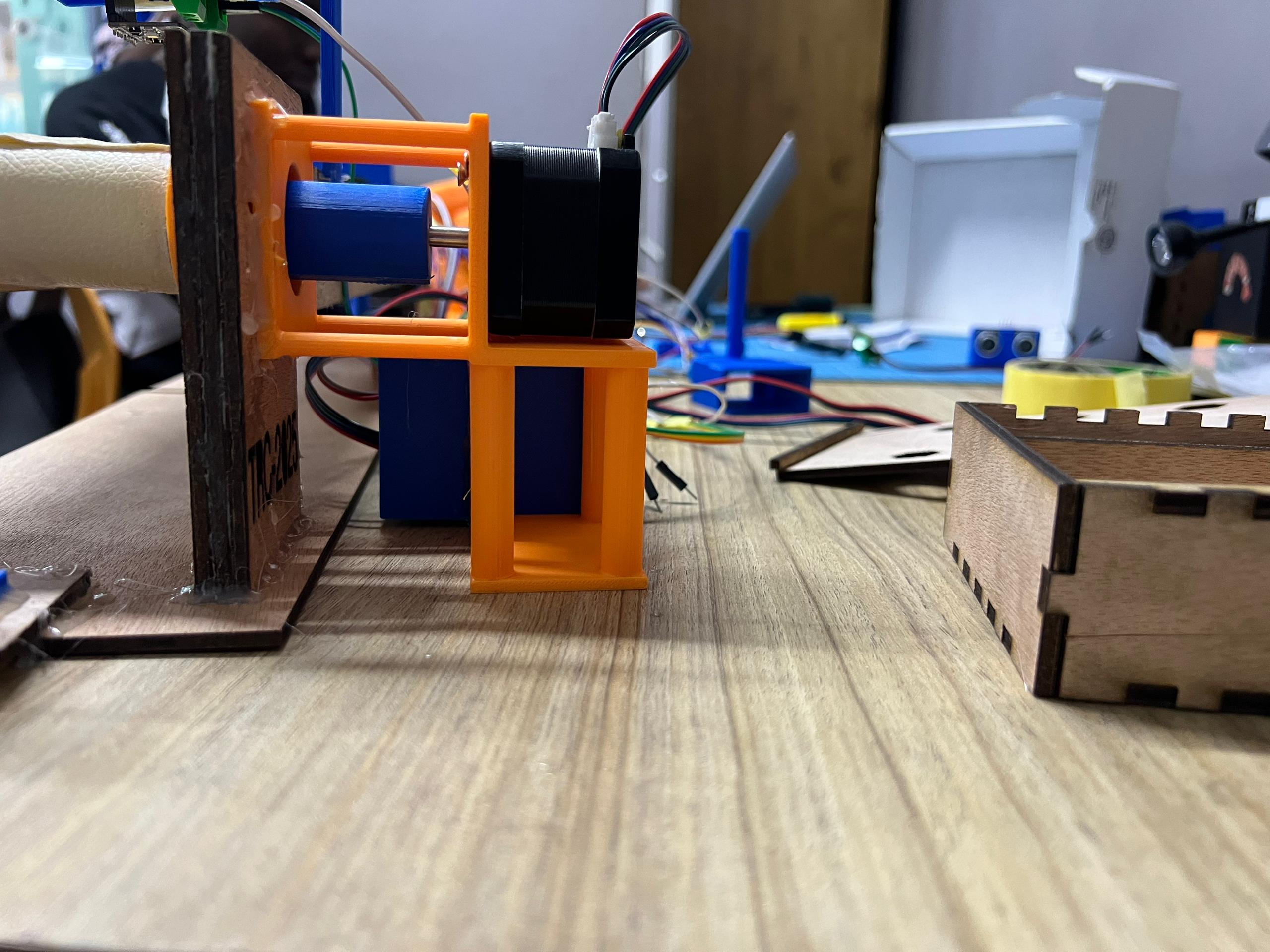
After defining a robust and balanced structure for the conveyor, we moved on to designing a system to enable waste mobility. The key component generating movement is a NEMA 17 motor. Initially, we had two drums aligned with the bearings. A leather belt was placed over the drums, serving as the moving surface. At this stage, the drum's movement drives the belt, which, like a pulley, moves all objects it carries.
Drum Design:
The drum is the cylindrical body in direct contact with the belt, transmitting motion. Its longitudinal ends fit into the bearings at the ends of the vertical supports. The main cylinder is 30mm wide, flanked by two 40mm-high discs to prevent overflows. There are two types:
Leader Drum: One end is longer (23/15mm) to pass through the 12mm-thick vertical surface and connect to the motor.Follower Drum: Both ends are 15mm long.
Process of Conception:
Energy Transmission System:
This video https://www.youtube.com/watch?v=5Xn26kxmX5U helped us explore various possibilities. Initially, we opted for a pulley-belt system, but we lacked customizable belts. We experimented with elastic bands, string, and chain systems, but these failed due to mechanical constraints, friction, or lack of adhesion. Finally, we opted for a safer solution: directly connecting the motor to the drum via a custom-designed Motor Support.
Position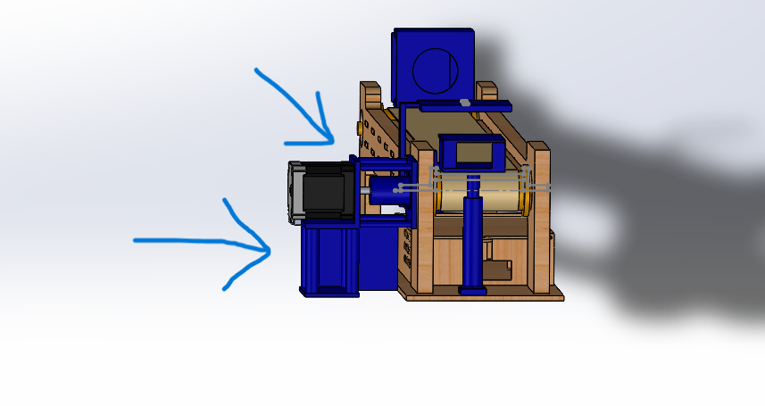
This structure allows us to fix the motor horizontally while maintaining the entire assembly vertically using four pillars in each direction.
Design Process:
The fixation of the motor and drum axles is ensured by a junction. It is a cylindrical body with two openings at its ends: one with a 5mm diameter for the NEMA motor shaft and the other with a 10mm diameter for the drum shaft. A tolerance of 0.1mm was later added to facilitate the insertion of each component into the two openings. Position
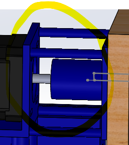
3D view
Assembly Process:
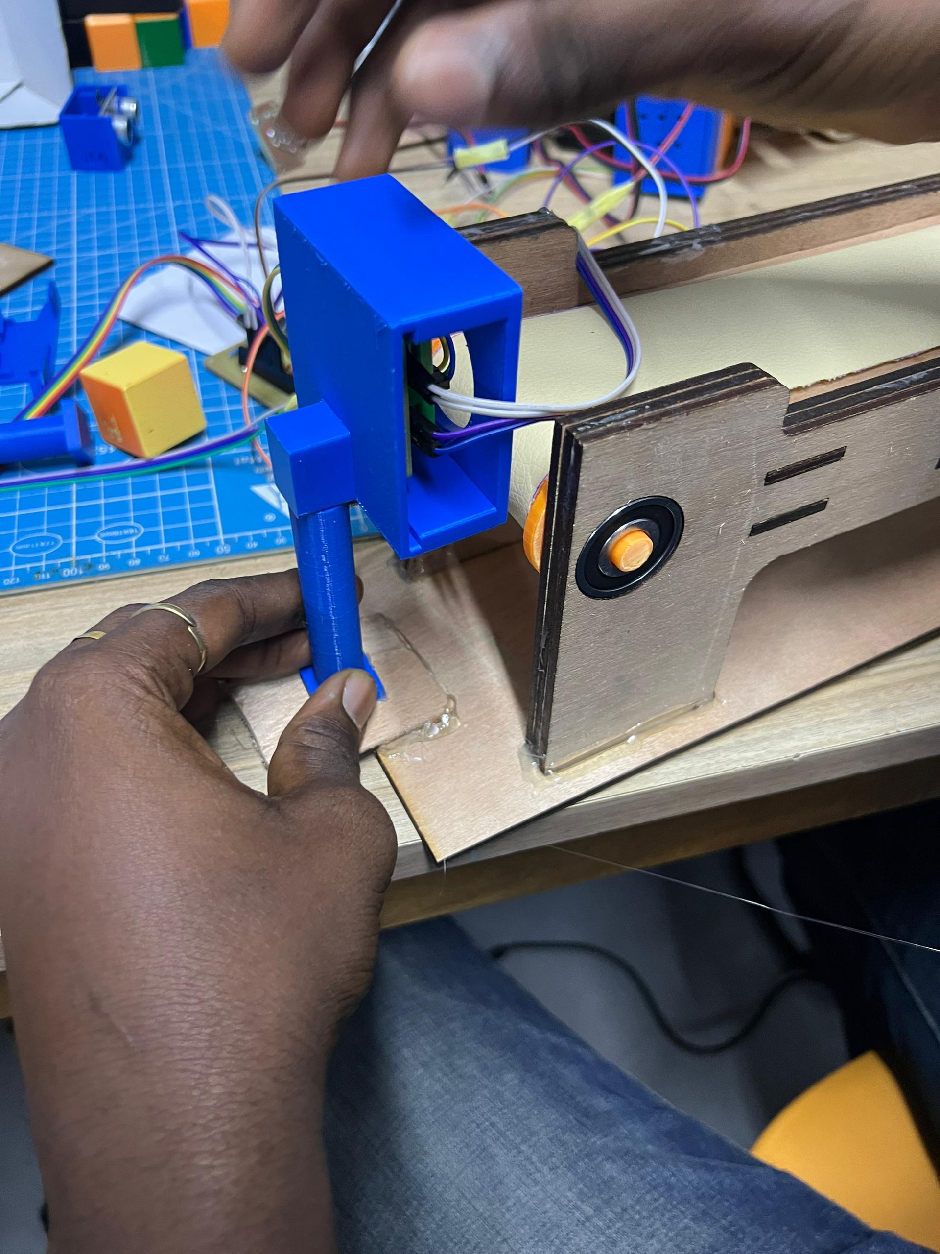
Sensors and Object Detection
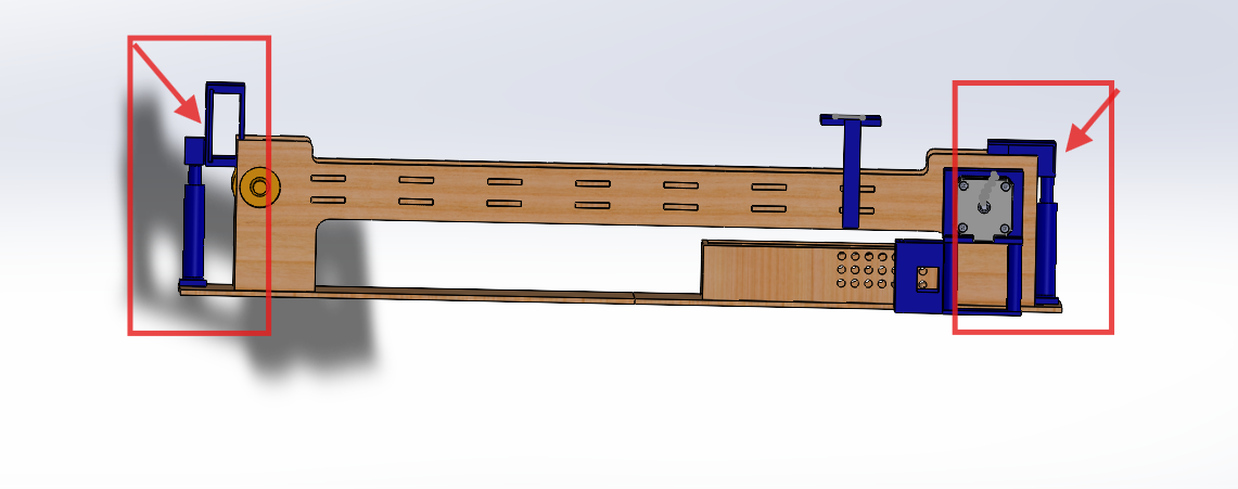
To enable waste detection on the conveyor, we collaborated with the electronics team to design a laser-phototransistor system. The laser emits a beam captured by the phototransistor. When the beam is interrupted, it indicates the presence of an object on the conveyor. To protect the components, the electronics engineers designed PCBs.
Our mechanical challenge was to design a mechanism to support this system, ensuring precise alignment. We designed adjustable supports with sliding cylindrical trunks in a screwable base.
Laser Port:
This is a platform with a rectangular configuration at the top, featuring an open hollow face for laser diffusion and a rectangular opening opposite for wiring. The length is approximately the sum of the lengths of the PCB coupled with the laser.
Design Process:
Phototransistor Port:
This is a rectangular platform designed to house the phototransistor PCB. Since the laser sensor is fixed, a sliding platform was added to adjust the horizontal position of the phototransistor for perfect calibration. A fairly large opening was also provided for wiring.
Design Process:
Base:
This is the main link allowing height adjustment, equipped with a cylindrical body to house the support and a 4mm opening for fixing the desired height.
Design Process:
Wiring simulation:
The carpet:
It's a surface that, as it rotates, pulls whatever it supports.
Conception:
Chassis Design
In total, the electronics team implemented five PCBs, including those for the laser and phototransistor. Our challenge was to design a chassis to house these components, ensuring protection, functionality, and aesthetics.
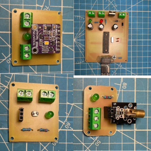
Motor Driver Box:
The motor driver is a PCB measuring 44mm in length and 57mm in width. We designed a small cubic box with two opposing openings on the lateral faces for wiring, a sliding lid, and small perforations for heat dissipation and compartment ventilation.
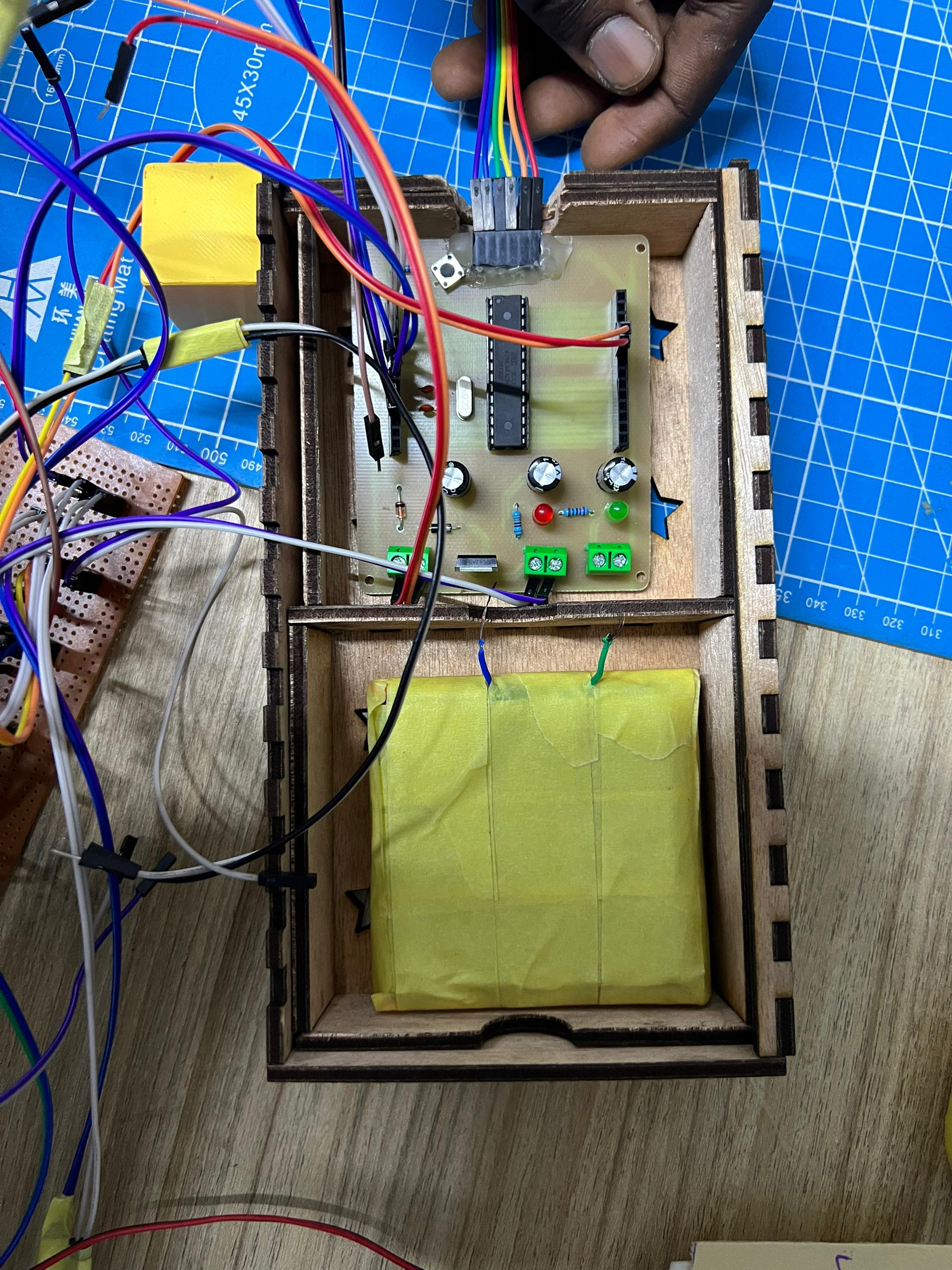
Central PCB Box:
This is the brain of all operations on the conveyor (similar to an Arduino replica). It measures 870x74mm and must be powered by a set of four Li-ion batteries. Therefore, we designed a box with two compartments (one for the PCB and one for the power supply), always with a sliding lid. Perforations were added to allow heat dissipation.
Download Resources:
Here is the link to download all the components.
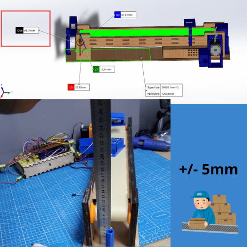
Note: We can observe that the distance between the mat and the ground in SolidWorks is approximately 95mm out of 100mm. This offset of 5mm is intentional because we noticed during assembly that the mat did not adhere perfectly to the upper horizontal support, resulting in a deviation of approximately ±5mm. Therefore, we reduced the measurement in SolidWorks to ensure that the mat is actually 100mm off the ground after assembly.
Solid Work Animation
Physical Construction Phase
Obtaining the Components
Once we had all the plans and parts ready, we moved on to the physical production phase. The sensor ports, drums, junctions, and other small components were 3D printed in PLA due to their small size. To achieve this, we first converted the SolidWorks files into STL format, then used the PrusaSlicer software to generate the G-code, which we sent to the printer (a Prusa MK4S Original).
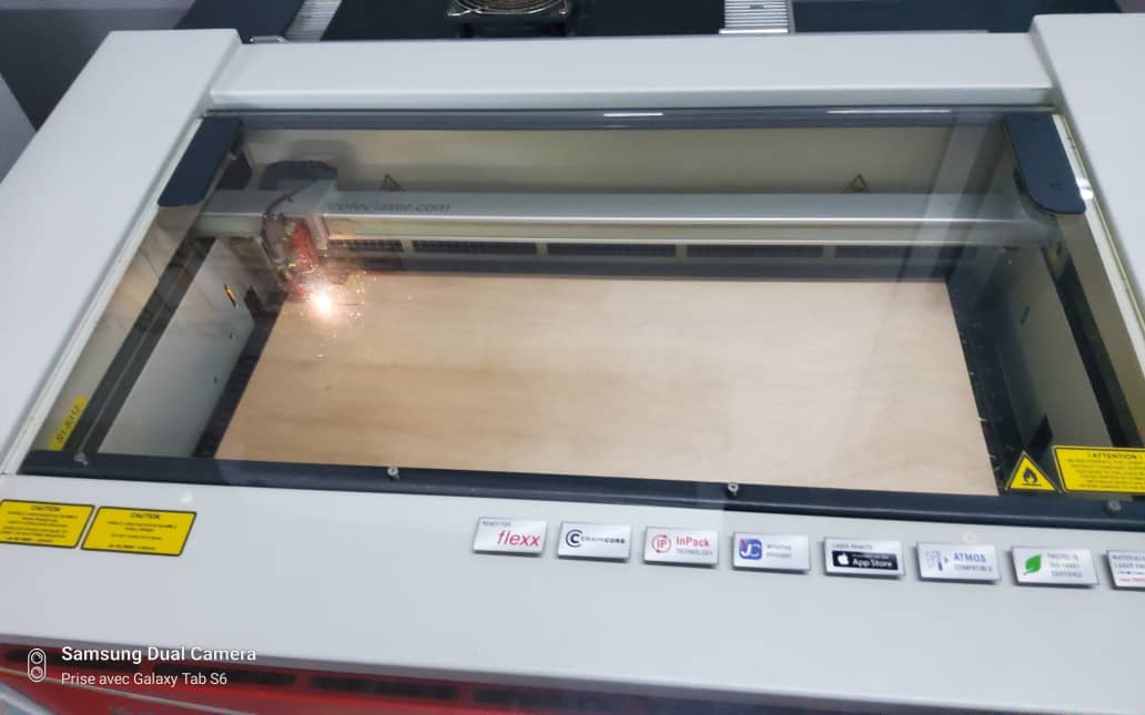
Laser Cutting
The vertical and horizontal planks, as well as the basal supports, were too large for 3D printing, so they were laser-cut from 4mm-thick plywood.
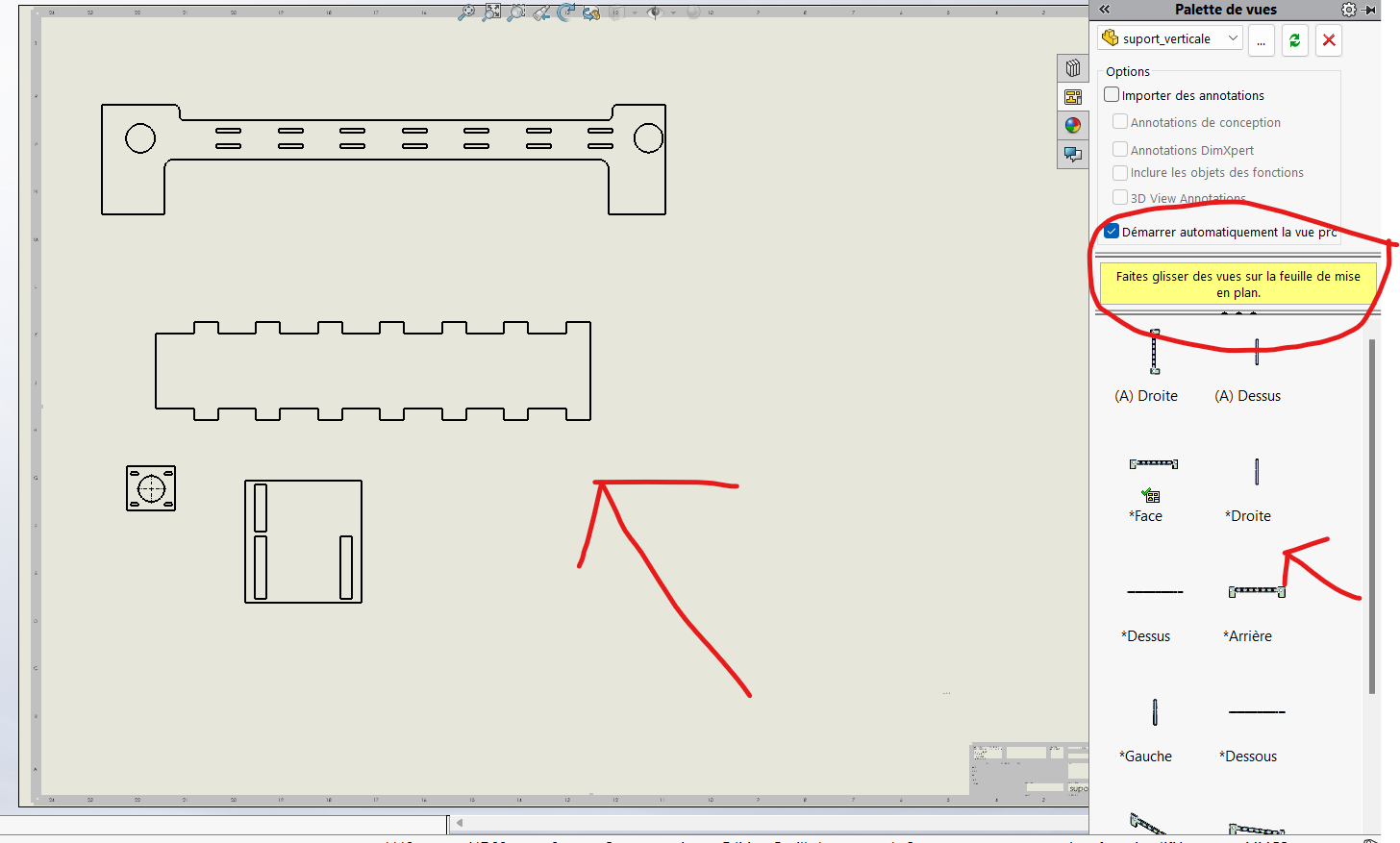
Process: To cut the planks, we followed these steps:
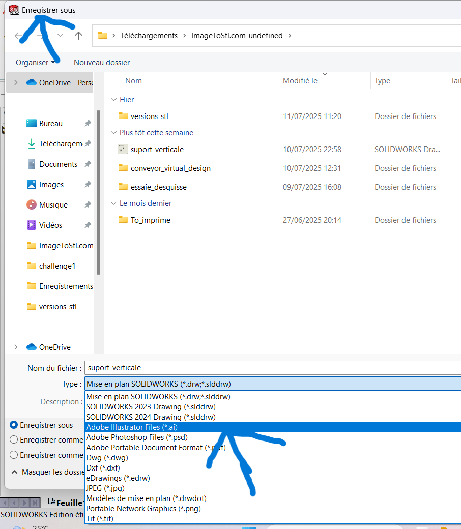
- Opened the detailed drawings of the parts.
- Exported them in SVG format.
- Configured the cutting parameters using Adobe Illustrator.
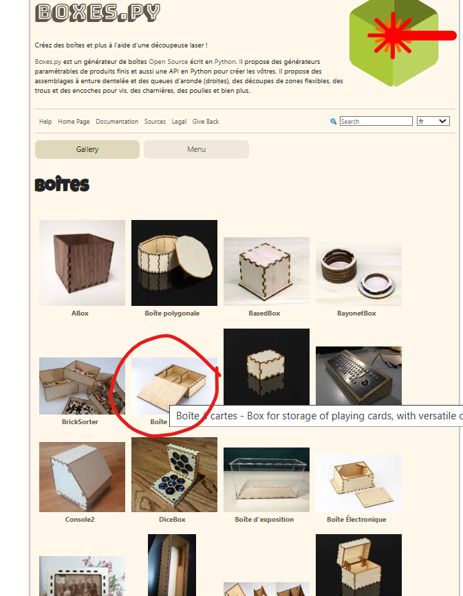
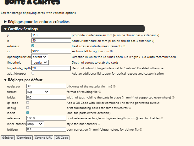
For the central PCB chassis, we used an open-source model available at Boxes Hackerspace Bamberg. We customized it by replacing the standard perforations with star-shaped and octagonal ones to give it a more "cute" aesthetic.
The files used for laser cutting are downloadable along with the other resources in the "laser_cutting_plans" folder. Once all this was done, we proceeded with the cutting and printing processes.
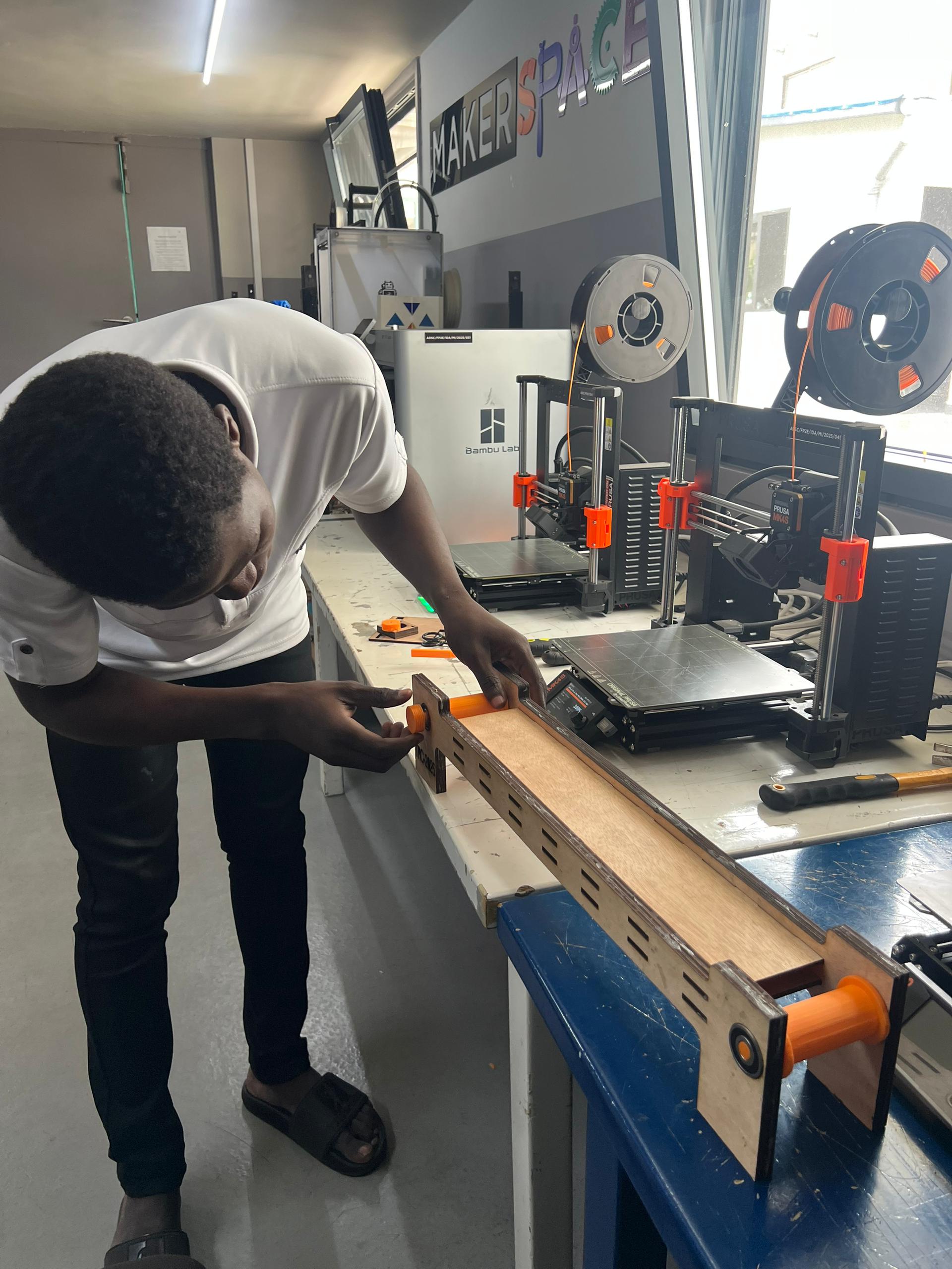
Assembly of Components
Once all the materials were ready, we began assembling the conveyor system. Below are the key steps we followed:
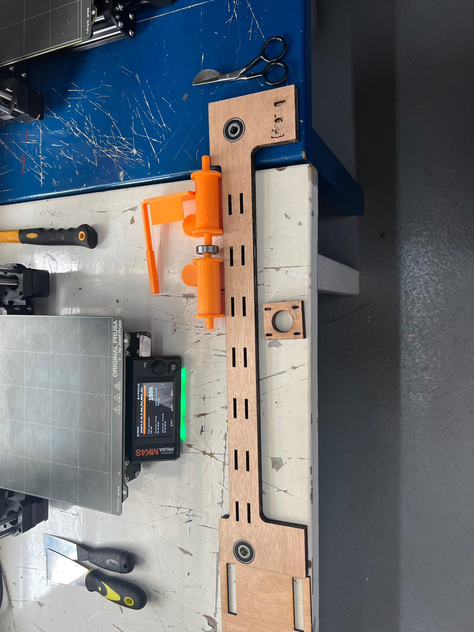
- Insertion of the Four Bearings into Their Dedicated Holes
- Mounting the Two Horizontal Supports into the Rows of Cavities on the Vertical Supports
- Insertion of the Drums into the Axis of the Bearings
- Superposition of the Second Vertical Face
- Fixation of the Color Sensor
- Fixation of the Motor onto Its Support and Then Onto the Conveyor
- Fixation of the Motor Driver Container Directly onto the Platform
- Fixation of the Sensor Bases
- wiring all component to central pcb (Performed by the Electronics Team)
- Calibration Test (Performed by the Electronics Team) This test ensured that the laser beam successfully reached the phototransistor.
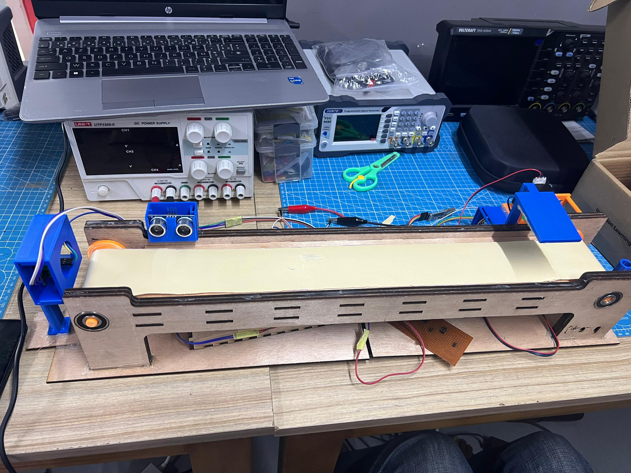
Final Result
Bonus: Automatic Sorting System
Once the conveyor was complete, we implemented an automatic sorting system to make the process smart and autonomous. For this, we opted to build the "SO-101 Robot Arm" project from Hugging Face, which involved creating and training robotic arms to perform precise tasks. The parts used are available via the link: SO-ARM100 GitHub Repository , and the assembly process we followed is accessible at: LeRobot SO-101 Documentation .
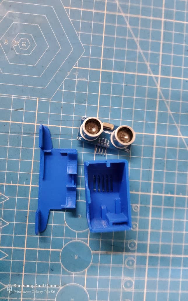
The new system works as follows: When waste arrives in front of the robotic arm, the conveyor stops. In collaboration with the mechanical team, we decided to integrate an ultrasonic sensor to manage this functionality. We designed and 3D-printed a custom support for the ultrasonic sensor using an open-source file.
Conclusion: A Journey of Innovation
This project was a testament to our ability to combine creativity, technical skills, and teamwork. Every step of the way— from ideation to virtual design, physical construction, and troubleshooting— taught us valuable lessons. As we prepare for the Tekbot Robotics Challenges, we are proud of what we have achieved and excited to showcase our conveyor system.