Part I Construction Documentation
Short Demo
Link to Download: Link to download
Method Using Successive Circles and Cuts
First Step: Creating the Three Base Circles
Description
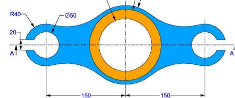
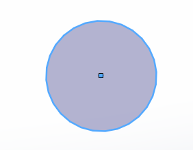
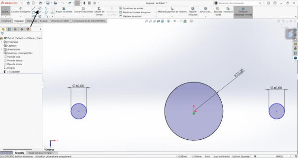
This step involves creating the three main circles to establish the base structure (see following screenshot) of the part: two lateral extensions and a central body.

Actions
Select the XY plane in SolidWorks.

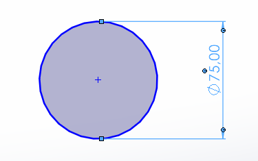
Draw the central circle with radius 75 mm at position (0, 0):
- select circle icon at the top left corner

- design your circle from choosen position
- Use the smart cotation to set a raduis

Draw the left circle:
- Radius: 40 mm
- Position: -150 mm from central circle center on X-axis
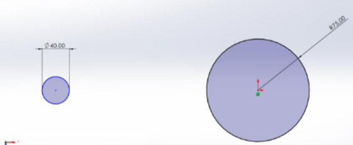
Draw the right circle:
- Radius: 40 mm
- Position: +150 mm from central circle center on X-axis
Result
Three circles positioned to form the dumbbell-shaped base geometry.
Screenshot 1:
Second Step: Adding Transition Circles
Description
Creation of additional circles to define transition zones and rounded shapes between main elements. The circles allow application of curvature radius in transition areas.
![]()
Actions
- Create new transition circles:
- Intermediate circles for smooth connections
- Radius: 75mm
- Strategic positioning for organic curves
- Apply tangent properties to circles
![]()
Third Step: Cutting Operations to Form Transitions
Description
Using additional circles to cut and recreate the part's characteristic rounded shapes.
Actions
First series of cuts:
Select circles to use as cutting tools
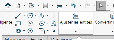
Select "Fit Entities" tool
Remove excess circle material
Second series of cuts:
- Refine transition shapes
- Create organic curves
- Eliminate unwanted intersections
Result
Dumbbell-shaped organic form with smooth curved transitions between central body and extensions.
Screenshot 3: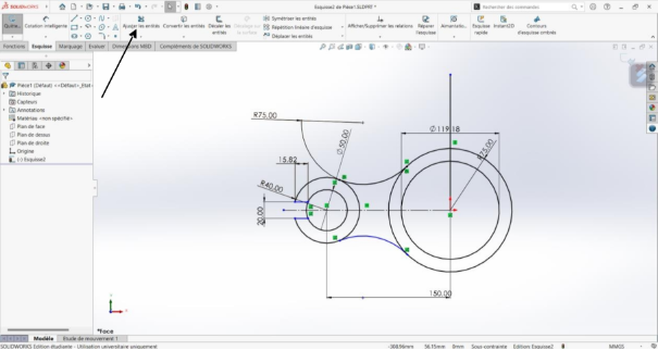
Fourth Step: Applying Symmetry Relative to Central Circle's (O,J) Axis
Description
Mirroring the completed portion relative to the central circle's (O,J) axis to facilitate reproduction of transition curves.
Actions
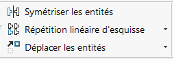
- Select portions to mirror
- Select symmetry axis
- Apply "Mirror Entities" function to selected elements
Result (See Screenshot 4)
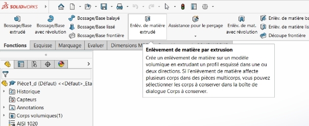
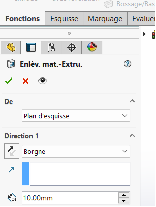
Fifth Step: Base Extrusion
Description
Transforming the obtained 2D part into a 3D component.
Actions
Select the three sketched circles
Use extrusion function
Set extrusion height to 20.00 mm
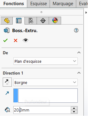
Extrude perpendicular to XY plane (along Z-axis)
Result
Formation of extruded part.
Screenshot 4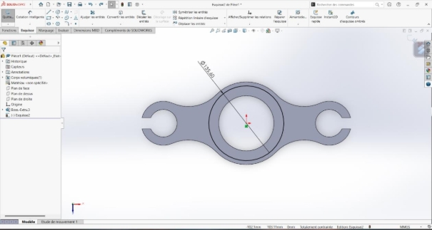
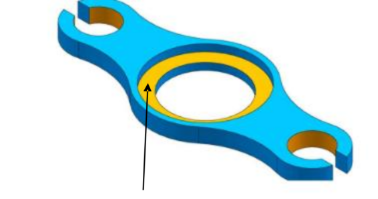
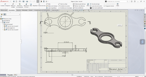
Sixth Step: Creating Main Central Hole
Description
Drilling the large central circular hole that forms the part's main feature, creating the hollowed area at the central circle.
Actions
Select top face of central portion
Draw centered circle:
- Diameter: Ø135.6 mm
- Position: geometric center of central portion
Use through-hole tool
Drill through entire thickness (10 mm)
Measurements
- Depth: 10 mm (through)
Result
Central circular through-hole in main part portion.
Screenshot 5 Location:
Seventh Step: Finishing and Material Properties
Description
Applying final finishes, verifications, material property definition, and mass determination.
Actions
- Geometric verification:
- Dimension control per technical drawing
- Check for geometric defects
- Create part drawing
- Material application:
- Selection: AISI 1020 Steel
- Density: 0.0079 g/mm³
- Automatic mass calculation
- Final adjustments
Screenshots 6: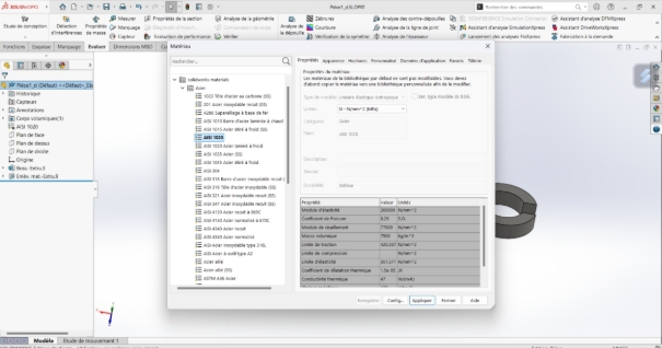
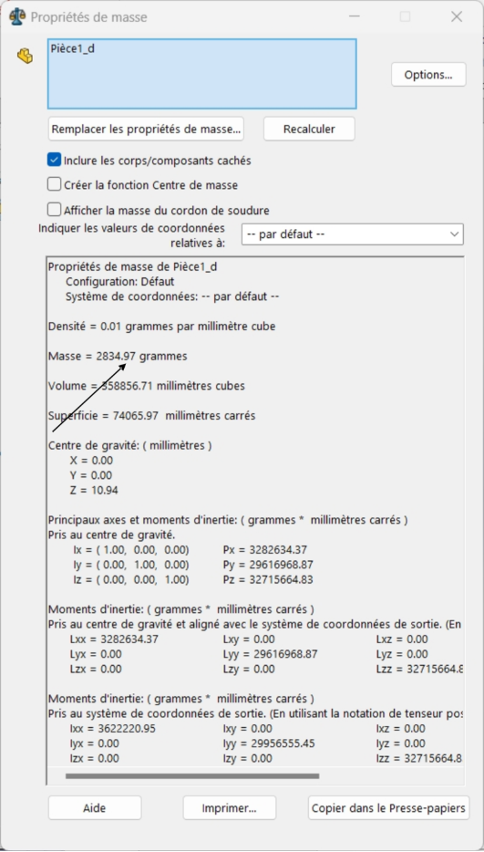
Final Measurements
- Material: AISI 1020 Steel (density 0.0079 g/mm³)
Obtained mass: 2834.97 grams